
Conversion of traditional buildings: guidance
This guidance provides a technical insight into the conversion of Scotland’s traditional buildings, balancing building regulation compliance with conservation. It promotes a holistic, risk-based approach to technical compliance in the performance of traditional buildings.
Part of

6.2 Building insulation envelope
Mandatory Standard
Standard 6.2
Every building must be designed and constructed in such a way that an insulation envelope is provided which reduces heat loss.
Limitation:
This standard does not apply to:
a) non-domestic buildings which will not be heated, other than heating provided solely for the purpose of frost protection
b) communal parts of domestic buildings which will not be heated, other than heating provided solely for the purpose of frost protection, or
c) buildings which are ancillary to dwellings, other than conservatories, which are either unheated or provided with heating which is solely for the purpose of frost protection.
6.2.1 Application of standard to conversions
In the case of conversions, as specified in regulation 4, the building as converted shall meet the requirements of this standard in so far as is reasonably practicable, and in no case be worse than before the conversion (regulation 12, schedule 6).
6.2.2 Commentary
Section 6 of the Technical Handbooks provides an overview of the approach to this standard and sets out the need for energy efficiency across both new and existing buildings but Standard 6.2 addresses the specific building fabric requirements and implications. In addition to addressing the U-values of all elements, consideration is also given to thermal bridging and airtightness which are incorporated within SAP, RdSAP and SBEM and recognised as integral parts of the energy modelling process.
Clause 6.2.7 recognises that achieving fabric improvements can be more complex in traditionally constructed buildings and makes it clear that these may need to be considered differently. Whilst achieving the U-values recommended in table 6.2 should remain the aim, it acknowledges that a flexible approach should be taken and where this isn’t possible, recommends that the ‘backstop’ U-values noted in clause 6.2.1 should not be exceeded.
A number of situations are identified which might be relevant, and these include:
- Where provisions under other legislation (such as any planning consents for listed building or those within conservation areas) may apply.
- Where improvement works might affect moisture movement or the permeability of existing construction.
- Whether improvement works can be carried out in a non-disruptive manner.
- Whether potential solutions are compatible with the existing construction.
Note that improvements in airtightness are not included in the above list but also provide significant potential for energy demand reduction without necessarily affecting the building fabric.
In the case of buildings that are protected due to their cultural significance, clause 6.2.7 of the Technical Handbook notes that where the significance is due to specific characteristics (such as materials, features or spaces), it may be possible to make greater improvements in areas of less sensitivity.
In addition, it signposts practitioners to this guide, and offers the following alternative ways of achieving energy demand reductions without affecting building fabric:
- Heating system improvements (refer Standards 6.3 and 6.4).
- Lighting system improvements (refer to Standard 6.5).
- The incorporation of renewable heating or on-site generation of heat or power.
SAP calculations are not required to prove compliance with Standard 6.1 for conversions as noted in the previous section, but through the use of SAP and RdSAP calculations more generally, there is capacity within Section 6 to offset higher and lower performing fabric U-values against each other to achieve the overall goals of energy efficiency as modelled.
It is important to note that while this works well in giving designers considerable freedom, it may require more consideration where the differences between U-values become too great. For example, this may occur due to a building’s cultural significance. Whilst numbers can be balanced in numeric models, the same is not true of buildings, heat, air and moisture flows. The practical implication of this is discussed below.
Where the cultural significance of a building or its features is a key consideration, it is possible that even the ‘backstop’ U-values noted in clause 6.2.1 may not be met in some areas. This creates two specific risks. The first is of excessive heat loss through these areas. The second is the creation of cooler surface or interstitial temperatures which could in turn lead to condensation and mould, depending on other factors such as building condition, moisture generation, airtightness and ventilation provision. These in turn could lead to decay of organic materials in the building as well as air quality and health impacts for occupants. This risk is specifically addressed in 6.2.3 and 6.2.4 below and further advice on condensation is provided in Section 3 of this guide at Standard 3.15: Condensation
In most traditional buildings, the most straightforward areas for insulating are often the roofs and floors. Although there are exceptions, this is because they usually have fewer technical and moisture risks associated with insulation, and because they will tend to have little impact on a building’s cultural significance. When looking at energy efficiency improvements across the whole building, therefore, the greatest gains may often be able to be made in these areas.
Conversely, walls often represent the greatest risks when insulating internally, as insulation can be more complex to install effectively, and the interventions required are more likely to impact on the character of a building’s interiors. For these reasons, it is expected that walls will usually offer the least potential to reduce energy consumption. Note that externally insulating walls usually carries fewer technical risks, but this may be outweighed by the visual impact this alteration would have on many traditional buildings, and the challenges associated with its installation which are outlined in Section 6.2.3 (9) below.
Timber sash and case windows account for most of the historic glazing in Scotland, formed sash frames which slide vertically in a timber casement (frame) set into the stone reveal of the opening.
Where a building is protected, there is normally a presumption against the alteration or replacement of original or historic windows that contribute to its cultural significance, although each case is considered on its merits.
The survival of historic glass and timberwork will tend to direct decision-making on what works can be carried out to windows, particularly in the case of listed buildings. Original or historic glass makes a significant contribution to the character of a building due to its age and the visual effect of imperfections in its manufacture.
A conservation-led approach would normally recommend that the same approach of retention and repair is taken to most traditionally constructed buildings. Where this is the case, there are several alternative solutions to achieving levels of thermal performance similar to new windows, identified in the HES Guide to Energy Retrofit of Traditional Buildings.
In some cases, the sashes or individual glazing panes may be replaced, along with other improvements to the original frames. Where it is permissible to replace windows fully, there is no reason they cannot meet the new-build equivalent levels of performance, and new technologies mean there can be a negligible visual impact on the traditional character of older buildings.
Airtightness is sometimes overlooked, but the potential to reduce energy consumption and improve comfort with relatively modest reductions in air leakage is considerable. Doing so has minimal visual impact and can be consistent with a conservation-led approach, but it is important to ensure that adequate ventilation measures are in place both for the building and its occupants.
In situ testing of U-values has become more common and HES Technical Papers shave shown that assumed figures for traditionally constructed walls can be unrepresentative of ‘real-world’ figures. Designers and other practitioners wishing to demonstrate good practice may want to consider measuring the ‘true’ thermal resistivity of traditional fabric elements rather than relying on potentially more onerous assumptions.
6.2.3 Issues to be considered
Typical risks in the conversion of historic/traditional buildings
1. Insulation improvements and moisture management
Adding insulation and airtightness measures to traditional buildings can increase moisture risks because in a warmer home, the warmer air can contain more vapour, and sealing up buildings reduces how moisture can escape.
An associated risk is that if some areas of a building are made warmer, but others are not (this could be different areas of a building, or different elements, like walls or windows) this increases the risk that warmer, moist air can find it way to the cooler areas and increase the risk of surface or interstitial condensation, mould and other problems.
Previous approaches to managing this risk have tended towards resisting insulation and airtightness to ensure that moisture is free to escape, as it has in the past.
The problem with this approach is that heat loss and air leakage are uncontrolled, so buildings can remain uncomfortable and expensive to heat, and energy consumption may remain high, contrary to both Scottish Government objectives of reducing fuel poverty and carbon emissions.
This guide supports practitioners in effectively improving buildings with insulation and appropriate levels of airtightness, whilst ensuring that the risks associated with excess moisture in the air and fabric of the building are adequately addressed.
2. Avoiding ‘cold spots’
Where the cultural significance of a building or its features is a key consideration, it may be that certain fabric elements will exceed the ‘backstop’ U-values set by Standard 6.2. In these cases, the designer should demonstrate how surface or interstitial condensation is avoided. Refer also to section 3, especially section 3.15: Condensation.
There are three key considerations in every case: surface temperatures, moisture generation and air movement. If the first of these is creating additional risk, the other two can often be controlled to minimise and avoid the risks.
For example, the designer may be able to show that there is no moisture generation within the space (but note that moisture can move through buildings if not controlled) or that additional ventilation will be introduced to remove moisture at source. In most cases, ventilation can be humidity-controlled to reduce energy consumption and improve efficiency.
3. Establishing accurate U-values
Studies by Historic Environment Scotland and others have demonstrated that assumed U-values for traditional construction may be over-estimated. This point is also noted in the context of the thermal capacity of masonry in 3.13.2 (Environment). In situ U-value testing will provide accurate U-values which will help with energy modelling.
In situ U-value testing usually takes a few weeks and requires specialist expertise and equipment which will represent additional costs and time to any project. However, where projects are large, or areas under consideration would be costly to insulate, demonstrating that less insulation is needed to meet a proposed U-value may be worthwhile.
4. Improving airtightness
Poor airtightness can be responsible for considerable levels of heat loss in existing buildings and can significantly undermine the benefits of any insulation measures if not tackled, so this should always be addressed as part of the overall aim of reducing energy consumption.
Additionally, air leakage within construction can lead to moisture entering the building fabric where it can condense and represent a risk in decay of timber and other components.
Airtightness works can be carried out with little or no visual impact on the appearance of the building, so are consistent with an approach which seeks to minimise changes to the character of buildings that are culturally significant due to their architectural or historic interest or their traditional construction.
Good airtightness can be achieved using traditional techniques and materials. For example, lime plaster is an effective alternative to modern membranes in some circumstances.
Note that airtightness does not necessarily imply vapour tight, so solutions should be sought which do not adversely restrict vapour movement.
Where buildings are insulated and made more airtight in pursuit of reduced energy consumption, there is a risk that moisture within the building and fabric cannot dissipate effectively if measures are not designed and installed correctly. This can potentially lead to problems such as interstitial condensation, mould and decay of organic components.
In order to balance the needs of energy conservation and building conservation, airtightness improvements must be accompanied by an understanding of moisture movement within the fabric, and a controllable, reliable and continuous level of ventilation. Refer also to the section below on managing moisture in walls.
Precise levels of airtightness are difficult to identify at the design stage but can be proposed and demonstrated using air pressure tests. These tests, if combined with air leakage audits and thermography, can be useful in identifying both air leaks (wanted and unwanted) as well as other building and workmanship defects, which can bring other benefits in the pursuit of high-quality construction.
5. Insulation choice
Beyond cost, there are many practical considerations that can impact on insulation choice, such as fire, compressibility and acoustics. Within the context of traditional and listed buildings, however, there are additional aspects which are worth considering.
Lambda values, which measure thermal resistivity, are an important factor in insulation choice. They feed into U-values which are the primary factor assessed by verifiers. When designing for buildings that are listed or traditionally constructed, it can be tempting to choose higher performance insulants to minimise visual or physical impacts of the installation itself, and perhaps to offset works elsewhere.
Lambda values, however, should be balanced against the fact that, where insulation is installed between a frame (such as framed walls, attics or suspended floors), any gaps around the edges of the insulation can compromise the effectiveness of the installation. Unless a perfect fit can be guaranteed, it may be better to use ‘soft’ or ‘semi-rigid’ insulation which can easily be installed to fit tightly and robustly in the long term. Note that some insulants that rely on gases for expansion and flexibility can experience shrinkage, brittleness and failure over the long term as these gases evaporate, leading to gaps around the edges of the insulation which undermine their long-term efficacy.
Where moisture movement through the fabric is an issue, an important part of the insulation specification is vapour permeability, capillary active capacity and hygroscopicity (allowing safe absorption and desorption of vapour). These insulation materials will protect timber frames (in walls, floors or roofs) in the long term whereas impermeable materials will ‘force’ moisture through the relatively permeable timbers, creating higher risks of moisture-related decay or insect attack.
The building warrant procedure does not require practitioners to consider the widely differing levels of embodied energy in different insulation types. However, the practitioner may choose insulation materials with a lower embodied energy quotient in support of a broader low carbon ethos.
6. Pitched roofs
Pitched roof – insulation at ceiling level:
Insulating at ceiling level results in a colder attic space above, meaning an increased risk of condensation and pipe freezing. Pipes must be well insulated, ceilings and services penetrations must be airtight, and ventilation is always required to dissipate moisture in the air. Electrical services should be protected from overheating either by being on top of the insulation, or within conduit or similar.
Lower pitch roofs can become colder and with less volume to disperse potential moisture, risks associated with moisture are increased. BS 5250 discusses the use of intermediate ventilation for low pitch longer span roofs. Refer also to section 3.15 (Condensation) in this guide.
Care must be taken to ensure that reliable ventilation pathways are created, normally at eaves and ridge level, benefitting from stack effect, or via cross-ventilation using low level ventilation on more than one side.
Ventilation pathways, where added to protect the structure, need to be carefully designed to avoid detrimental visual impacts.
Pitched roof – insulation within rafters:
Insulating between rafters often means the removal of some or all existing plaster finishes. Removal can be avoided in some cases where access can be created by partial removal of plaster. Many buildings may also be found to have modern plasterboard where complete removal allows for the works to be undertaken without impacting on the quality and authenticity of the building.
Care must be taken to ensure that reliable ventilation pathways are created on the cold side of the insulated sections, with openings at both ends. Ventilation pathways can be particularly difficult to create and maintain around dormers and rooflights. Adding vents in areas to be insulated may be difficult to achieve without impacting on the character of a building and should be carefully considered.
Where the ceiling or roof finishes are not significant, an additional layer of appropriate rigid insulation can sometimes be applied above or below the rafters to address thermal bridging and improve thermal performance further. This can, however, have knock-on effects on adjacent construction which need to be managed.
7. Flat roofs
External upgrade of flat roof
In some cases, the existing external covering may need to be repaired or replaced, or there may be an unsuitable modern finish to be upgraded, in which case insulation upgrading may be easier to achieve from outside as part of the works. This may also be a suitable option where the internal ceiling finishes are of greater architectural or historic interest than the external finish.
Where insulation is installed from outside, it should be easier to ensure all areas are fully and neatly insulated, leaving adequate space for ventilation below sarking. Note that no vapour control will be possible so ventilation of space immediately beneath sarking becomes even more important.
If upgrading from outside, it may also be possible to insulate over the existing deck to create a warm roof. However, this will mean forming a new roof deck which will change the appearance and be likely to create knock-on effects on adjacent structure and finishes.
Internal upgrade of flat roof
Upgrading insulation from inside ensures that external finishes will be undisturbed but requires the formation of access through the existing ceiling. This can be more challenging where the ceiling clearly has architectural or historic significance. On the other hand, effective insulation of the space usually requires greater levels of access, and thus a balance needs to be struck in each case between heritage impacts and operational/efficiency benefits.
Where insulation is to be added, a key risk to flat roof construction is a reduction in the air flow needed to dissipate moisture which can accumulate on the underside of metal or other impermeable finishes. This moisture can lead to corrosion of the roof finish and decay of the underlying sarking. Thus, maintaining adequate air flow is the priority with any detail. Further advice on moisture management in cavities is contained in Section 3: Environment.
If there is no existing ventilation, or if it needs to be improved, it is important that the visual impact of the works is considered, particularly if they are likely to affect the character of a listed building.
8. Walls and moisture risk
Risks associated with walls and the presence of moisture should be assessed in conjunction with both externally and internally insulated wall sections.
The modern understanding of moisture risk in construction is that as warmth and moisture inside buildings will tend to expand outwards, it makes sense to install vapour barriers and control layers (VCLs) on the warm side of the insulation. This prevents this internal moisture getting into the building fabric where it could cool and form interstitial condensation.
However, advanced hygrothermal modelling demonstrates that equal, and sometimes greater risks can come from wind-driven rain entering walls from the outside, working its way inwards and becoming trapped. This risk is relatively minimal in most modern construction which tends to be formed from separated leaves of construction with cavities which prevent the ingress of this external moisture.
However, most traditional construction is largely monolithic, and in these cases, it is essential to understand that moisture risks are associated with both internal and external moisture loads. The risk is greater in exposed areas, where masonry is particularly porous, and/or where impermeable materials (such as cement renders or pointing) have been used which can let moisture in through cracks but will then tend to trap it within the construction.
As such, maintenance of traditional walls becomes an important part of assessing moisture risk and the appropriateness of insulation options, alongside effective rainwater management and internal ventilation provision.
It follows that, while well-installed VCLs can serve to prevent moisture transfer from the inside, their use (along with other impermeable materials) can increase the risk of moisture related problems if the moisture comes from outside and/or if the VCL is compromised.
Thus, moisture risk is better managed through the following strategies:
- Ensuring the external face of walls is kept in sufficiently good condition (along with rainwater goods etc.) to reduce moisture ingress, allow moisture to readily escape, reducing the risk of moisture becoming trapped.
- Ensuring a reliable and responsive or continuous level of ventilation internally will manage internal moisture loads through extraction of moist air.
- Vapour permeable, capillary active and hygroscopic materials can safely absorb, transfer and desorb (release) moisture, and can be used to reduce moisture build-up risk without the need for cavities, although this will depend on the level of moisture pressure and permeability of materials chosen.
- Cavities, (e.g. behind lath and plaster) prevent transfer of moisture across the construction and should be able to dissipate moisture, depending on how well ventilated and connected to other spaces they are.
- Note that these strategies do not ‘force’ moisture within a wall in a particular direction but rather allow the moisture to dissipate freely.
- Note too that these strategies do not include deliberate high levels of air infiltration, as this allows excessive and uncontrolled heat loss, can cause other problems and does not reliably dry out buildings.
The preferred technique to insulate internally in most cases is to install vapour permeable, capillary active and hygroscopic insulation direct against a wall which has been prepared and has no residual impermeable finishes. It is important that the external condition of the wall and suitable ventilation is also specified as noted above. This approach is shown in illustrations 89, 90, 92, 95, 96 and 97.
An alternative approach is to maintain a cavity between the masonry wall and form a separate insulated layer. This could be a free-standing frame with insulation infill, or an insulation layer installed against battens, for example. Despite being commonly used, this solution doesn’t represent best practice in building conservation but can be useful where the masonry is unavoidably damp. Where this solution is employed, it is critical that a robust ventilation proposal is included for the cavity. This approach is shown in illustration 91 and 94.
For further guidance on condensation refer to section 3.15: Condensation.
9. External insulation to walls
The external elevations of traditional buildings are key to appreciating their architectural and historic interest and their contribution to Scotland’s historic environment. For this reason, it will be clear in some situations that the application of external wall insulation (EWI) and finishes will have a negative impact on the appreciation of a building.
However, EWI may be acceptable in situations where the building is already rendered, painted or covered in a finish that can be replicated over a layer of insulation. It may also be acceptable where there is evidence that previous external coating existed.
EWI may also be acceptable on side or rear elevations, on extensions, or where cultural significance is lower. EWI is commonly formed by insulation boards and render but may come in the form of an insulated render, which can replace existing render finishes with little or no change in external appearance.
Where EWI is permissible, it has number of advantages over internally applied insulation (IWI). These are described in the section below in the context of the potential disadvantages of IWI which should be carefully considered in each case. Successful installation of externally applied insulation can require extensive preparatory works which are not always fully anticipated, along with the need for careful detailing at critical junctions. These are discussed in 6.2.4.
EWI may be subject to constraints in relation to fire and structural issues which will need to be resolved in all cases.
10. Internal wall insulation
Internally applied insulation:
Where EWI is not an appropriate option, the application of internal wall insulation (IWI) may be considered. By comparison to EWI, IWI has some advantages, which include:
- Insulation can be installed in one property, or even one room only where needed.
- Planning permission is usually not required, although both planning and listed building consent may be required in some situations,
- Fewer restrictions on working related to the weather or external temperatures.
- No restrictions related to access, whereas anything above ground floor normally requires scaffolding when working externally.
However, there are several potential disadvantages associated with IWI, any of which may lead to IWI being overly difficult in practical or technical terms, or because of the physical or visual impacts it will have on the building’s interiors and their features:
- Works can involve significant disruption to occupants including decanting,
- Damage and disruption to internal finishes, which may include historic plasterwork and paintwork, timber linings or mouldings associated with historic decorative schemes. In some cases, these may be more significant to a building than its external appearance, and consent may be required for internal changes to those buildings protected by listing,
- Loss of space internally can be unacceptable in certain circumstances,
- Well designed and installed EWI fundamentally keeps walls protected, dry and ‘warm’ with reduced moisture risk. IWI inevitably creates ‘cold’ walls which are inherently more susceptible to moisture risk, for example, to embedded timbers which penetrate through the internal insulation layer. The level of risk can be assessed and managed with appropriate solutions but must be addressed within any IWI design strategy,
- Window reveals usually represent thermal bridges in both IWI and EWI installations and must be included in the insulation strategy. They can require specialist materials or approaches internally to avoid compatibility issues with windows, paneling and shutters,
- Internal partition walls and floor constructions which abut external walls present thermal bridges. In some cases, these can represent a significant heat loss problem and if not addressed can lead to cold internal surface temperatures which can cause interstitial or surface condensation, mould and other moisture related problems.
Unlike EWI, IWI provides no additional protection from the weather. It is important that any IWI design includes for appropriate protection / remediation of the external wall finish where the external condition of the walls is poor, maintenance has not been undertaken, where walls are particularly exposed, and particularly within the context of more windy and rainy weather under climate change.
IWI separates the thermal mass in the walls from the space inside, which needs to be considered where thermal mass is part of a thermal comfort strategy.
11. Other wall types
Almost all traditional (mainly pre-1919) buildings in Scotland have solid masonry walls, with or without external render and with or without internal linings, although many will have undergone alterations since construction.
However, there are some buildings that may have alternative wall construction. Before stone buildings became common, traditional buildings in Scotland were largely built of timber with earth or lime infill and some of these survive, as do many buildings of earthen construction, brick, cement-mortared, cavity walled and other ‘non-traditional’ pre-1919 constructions.
These wall constructions are not addressed in this publication, and the reader is directed to specialist practitioners who have experience with such constructions.
12. Windows and doors
Windows and doors represent an important part of the character and significance of traditional buildings and care may therefore be required when considering upgrading or alterations. However, along with airtightness, windows usually represent the ‘weakest link’ in the thermal performance of a building. With the need to think holistically about overall building performance therefore, it is important to attempt as effective an upgrade as possible, taking into account any special considerations like listed status.
Modern replacement windows typically tend to be designed to different proportions, with different opening arrangements and thicker frames and glazing bars, meaning they can have a detrimental visual impact on many traditional buildings. Where replacement is permitted, options exist to install windows which are extremely close in appearance while providing considerable thermal improvements.
With listed buildings, there is a general presumption in favour of retaining and repairing existing windows where these contribute to the special interest of the building due to being original or historic fabric.
Traditionally, this has been because the retention of original or historic windows maintains the authenticity of a building by preserving its historic fabric, but it also because the quality of naturally grown close-grained softwoods used in historic buildings is recognized as being much more durable than modern timber. It is also worth bearing in mind that retaining and upgrading windows also avoids the embodied carbon associated with the manufacture and transport of replacement units.
Historic Environment Scotland’s Guide for Practitioners 3: Conservation of Timber Sash and Case Windows (2002) provides advice on the inspection and repair of historic windows.
Several Historic Environment Scotland (HES) Technical Papers (TPs) deal with the thermal upgrading of traditional windows and should be referenced, including TP 01, 09, 20 and 23, while several others review the thermal performance of windows within the wider context of the whole building. The subject is extensively discussed in the HES Guide to Energy Retrofit of Traditional Buildings (2021) in which the measured U-values of various measures are given.
Managing Change in the Historic Environment: Windows (2018) provides guidance on the contribution of historic windows and outlines principles of repair and replacement in the context of national planning policy.
Although there is a presumption in favour of retention, an unimproved single glazed window will not be able to comply with Section 6 requirements. However, a range of measures are available which can improve their energy efficiency.
Windows gain and lose heat through a variety of mechanisms, only one of which is the U-value of the window component itself. Where simple U-value-based compliance with building standards is not possible, a strategy involving the alternative measures noted below and in 6.2.4 should be discussed at an early stage with the verifier.
Air leakage through old windows and doors can be significant, and modern draughtproofing can effectively reduce heat loss without affecting the visual character or function of these elements. Draught-stripping of doors and windows is covered in BS 7386: 1997. While draught-stripping is valuable for energy efficiency, it does reduce the free air within the building and the practitioner should demonstrate how the proposals manage this, taking general moisture management, indoor air quality, and combustion appliance air supply requirements into account.
Significant levels of heat loss and cold ingress can occur between a window and the adjacent wall on all sides. This is unrelated to the window itself and can lead to condensation, mould and decay on adjacent finishes when cold air enters the building and cools the back of thin internal linings. Although it can be disruptive to historic fabric and finishes, improvements can be made by removing internal reveals and sills, insulating and sealing the window perimeter against air ingress (e.g. using natural insulation between window and masonry, and tape across the internal gap) before re-installing the linings.
Windows gain and lose heat differently according to their orientation. South facing windows, even in Scotland, can gain as much heat as they lose over the course of a year, whereas north facing windows only ever lose heat. Where the primary elevation of a building faces south, for example, but north facing elevations are considered of lesser importance, it may be possible to adopt a varied approach to thermal upgrades which permits greater thermal upgrading on north and other elevations, whilst remaining more constrained on the south facing elevation.
Secondary glazing can provide an effective way to reduce heat loss without altering original windows, nor significantly reducing light levels or views. There are many types available with different fixing and opening arrangements. Care should be taken to ensure that new glazing units do not unduly affect the visual appearance of windows and internal finishes, nor negatively affect practical issues such as fire escape, cleaning and maintenance, ventilation and the function of other components such as shutters.
Slim profile double glazing or vacuum glazing can be used within some traditional window sashes as a direct replacement for single pane glazing. This can significantly improve the overall thermal performance of the original window while retaining the existing joinery. Note that replacing whole sashes or units is more effective thermally, but glazing upgrades represent a good compromise as an alternative to replacement of the joinery. Designers should satisfy themselves that any relevant manufacturing standards have been met when specifying glazing upgrades.
While there is variability between windows gaining and losing heat in the day, all windows lose heat at night, except in the very warmest weather. For this reason, measures to retain heat at night are particularly helpful and will reduce heat loss and energy consumption even if not recognised by conventional energy models.
Shutters, blinds and curtains can all help achieve this on their own or in combination. Shutters normally have the greatest potential and should be used or brought back into use if possible. Their performance can be enhanced by insulating panels and draught stripping. Similarly, insulating blinds are available, and curtains can be lined and insulated. Trapping air around the edges to create a sealed cavity helps create a buffer which reduces heat loss.
Windows are normally considered in terms of how they can be improved to retain heat, but the onset of climate change will occasionally require an appraisal of increased risks associated with overheating in buildings. This risk is likely to be lower in traditional buildings with smaller windows and heavyweight stone walls, but needs to be assessed in all cases, and especially where the building has larger, south-facing windows. In all circumstances, windows (and rooflights) should retain their full capacity to ventilate rooms.
Internal shading options, such as shutters, blinds and curtains may be useful, especially where they can form an effective buffer zone. Note that thermally improved windows will better resist incoming heat, as well as outgoing heat, so can be a useful part of a robust overheating strategy.
External shading is more effective in preventing overheating but rarely considered in Scotland. More guidance on internal and external shading can be found in Section 3: Environment: Standard 3.28 Overheating risk.
Increased condensation and subsequent decay of timbers can result if windows remain unimproved, but the rest of a building has been subject to thermal upgrades. This means it is important that the window is properly maintained and managed (e.g. from ventilation).
13. Solid floors
Energy efficiency improvements to solid floors should be considered on a case-by-case basis considering the level of intervention required to achieve an upgrade in thermal performance. This should be considered in the context of the significance of the floor and building, balanced against the long-term future of the building and comfort of its occupants.
There are four approaches to the thermal upgrade of solid floors, depending on the balance between significance and need for improvement:
1. The floor finish is significant and cannot be moved. In this case, no change is acceptable other than for repairs and maintenance.
2. Where the floor finish is significant but can be moved, it can be carefully set aside, a new level excavated, insulation added, and the original finish re-laid to the same level if required.
3. The floor finish is not significant, and overlay is possible. In this case insulation and a new floor finish can be overlaid. Interaction with adjacent floor levels, stairs, internal doors, skirtings all require consideration.
4. Where the floor finish is non-significant and overlay is not possible excavation will be required with new insulation and floor finish. Practical or financial reasons may prevent this route being possible.
An important issue in traditionally constructed buildings is how to resist upward ground water pressure. Many traditionally built buildings have neither a formal damp proof course (DPC) in the walls, nor a damp proof membrane (DPM) in the floor, yet have remained dry for over a hundred years or more.
In contrast, all modern buildings use DPCs and DPMs to resist upward moisture pressure and this approach is embedded within the Technical Standards. This method works well when designed as an integral part of the overall design but can be problematic when applied retrospectively to older buildings which didn’t previously operate like that. For example, applying DPM to a ground floor (which didn’t previously have one) can direct ground moisture to the building perimeter and force it up the walls which have no DPC, causing rising damp.
In general, the conservation approach is to adopt traditional techniques, avoiding formal DPCs and DPMs. However, where this approach is adopted in conversions, it should be made explicit how upward moisture from the ground will be resisted in both walls and floors.
For example, where no modern membranes are to be used, the designer should demonstrate how groundwater pressure will be relieved. This is most commonly done via external perimeter drainage such as a ‘French drain’ or similar, but this can be combined with drainage beneath the floor, free draining aggregates and other techniques such as lowering adjacent ground levels. Note that the need for radon protection, long term evidence of damp or high groundwater pressure can outweigh the above considerations in some situations.
While ‘French drains’ are a common solution, they can themselves represent a problem if not designed and installed correctly. All drains should be robust and laid to adequate falls away from the building, with suitable rodding access and well maintained. They should not be laid where there is potential for flooding, and there are many situations when they are not practical, for example when the building is directly against a pavement. Care should also be taken in all cases not to undermine the building foundations.
Where changes are proposed for solid floors (either excavation or overlay) the potential to include drainage, underfloor heating and/or service runs should be considered where this may help. Reducing the thickness of insulation to accommodate services should be avoided where possible.
Where solid floors remain uninsulated, they may increase the risk of cold and damp in adjacent solid walls at low level, if not thermally separated.
Further guidance on moisture in solid floor floors can be found in Environment: Sections 3.4 (Moisture from the ground) and 3.15 (Condensation).
14. Suspended floors
Energy efficiency improvements to suspended floors should be considered on a case-by-case basis considering the level of intervention required to achieve an upgrade in thermal performance. This should be considered in the context of the significance of the floor and building, balanced against the long-term future of the building and comfort of its occupants.
Solum ventilation
The most important consideration with suspended floors is to ensure that there is an uninterrupted and reliable flow of air beneath the floor across the entire solum. This is to ensure that any moisture within the underfloor cavity and floor construction can safely dissipate.
Note that this includes both suitable ventilation around the perimeter, and adequate pathways through the solum itself, via gaps or holes in structural internal sub-walls.
Sub-floor or solum vents (air bricks) will almost always exist and should be checked for adequacy and supplemented with additional vents if necessary. Section 3.4.4 of the Technical Handbook provides guidance on modern expectations for the ventilation of suspended floors.
Solum vents can become blocked or obscured by rising external ground levels or debris, applied finishes such as paving or tarmac, or physically blocked to reduce cold air ingress. They are also blocked when extensions are added with no provision for extending the air pathway below the new construction.
Sometimes, air bricks are set level with the floor joists meaning that insulating between joists would block the pathway of air. In these cases, periscope vents or similar can be used to divert air beneath the insulated joist level.
Once well insulated, the solum can become very cold, so the same comments apply here as for the attic of a cold roof. Plumbing should be well insulated while electric cables should be below the insulation or kept within conduit to prevent overheating.
Floor joist decay
It is important to check all existing floor joists for decay before proceeding with insulation works. Risks are highest around the perimeter, and especially where timbers are in contact with potentially damp masonry.
There are two approaches to insulation:
- Suspended floors can either be insulated from below, or from above.
- Insulating from below is easier to do if there is enough space to work, and there is no damage or disruption to the floor finish (which may be culturally significant) except through the access points needed. For example, some floorboards can’t be lifted without causing damage to them and some floors may be sufficiently important to recommend against insulation due to the disruption it will cause.
Insulating from above is sometimes necessary if there is insufficient access from below. This involves removing part or all the floor finish and installing insulation from above, before re-laying the original floor or installing a new floor finish. Risks of insulating from beneath usually relate to working in confined spaces, while risks from working from above include instability of joists and falling through gaps.
6.2.4 Recommendations to meet the standard
Whilst there may be situations where no improvement can be made to one or more elements of a building, the drawings shown in this section present some form of improvement to each element.
The illustrations are not specifications and should not be used as standard details. They do not give precise U-values, materials specifications and they do not provide exact dimensions. They are intended to be indicative of the principles behind the detail and contain explanatory notes and text. Note that they cover composite situations (a particular wall detail with a particular floor detail) but these are interchangeable while the importance of showing junctions is to highlight the need to address thermal bridging where relevant. The advice contained within the following illustrations cannot cover all situations but indicates typical issues outlined in the preceding sections. It is important to note that these illustrations cannot show the interactions of building fabric with heating and ventilation systems, nor with specific issues of cultural significance. It is expected that designers and practitioners will engage with specialists where necessary and consult with verifiers in all cases to establish specific details for individual buildings.
a) Internally insulated walls, floors and roofs
For externally insulated walls, refer to 6.2.4 b) below.
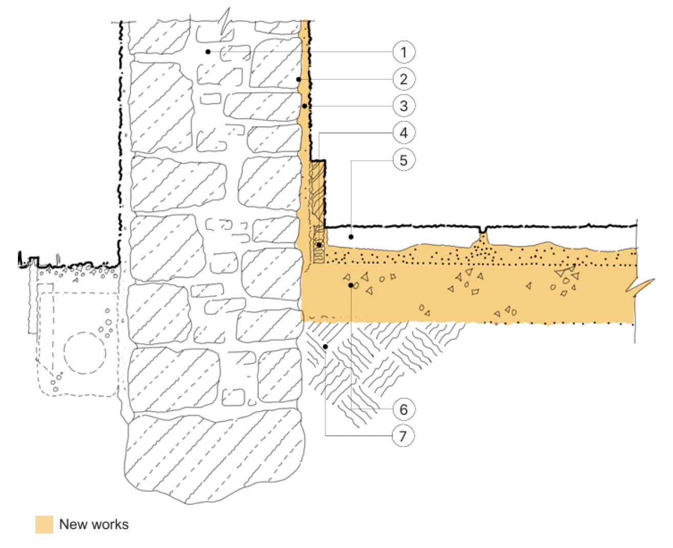
Drawing notes:
1. Existing solid masonry wall.
2. Existing internal plaster removed (could be left in place subject to providing sufficient key).
3. New, applied insulated plaster with finish coat and decoration.
4. Perimeter insulation strip (non-organic) covered by skirting board.
5. Existing floor finish (e.g. flagstones) carefully removed and re-laid with lime grout at original level to new lime-based mortar bed.
6. New granular, free-draining insulation (e.g. foamed glass, vermiculite).
7. Existing/undisturbed substrate.
Note:
- Insulated plaster should be returned into all door and window reveals.
- Perimeter drain externally to remove groundwater pressure and ensure wall base and internal floor insulation remains dry.
- No DPM or DPCs required, but designer must demonstrate how ground remains dry if French drain is not used as shown.
This shows a solid floor surfaced with historically significant stone slabs that have been re-laid after excavation and the installation of free draining mineral bead-type insulation. It also shows a solid wall, with internal plaster removed, and direct applied IWI (insulated plaster) added in lieu. Internal excavation should not undermine the wall foundations.
There are many potential variations of the illustration above. The external render as shown could also be replaced with an insulated alternative which would improve the overall thermal performance of the wall. It may be that a perimeter drain externally is not required if other measures are in place to ensure the area around the building and beneath the floor remains dry. Note that a DPC within the wall as would be expected in a modern wall is not recommended but refer to the discussion of this subject in 6.2.3.
The illustration does not show where service runs might go, and it is worth noting that socket boxes, for example, embedded in the insulated plaster would constitute a significant thermal bridge. Avoiding this via surface mounted services may not be acceptable, although all services could be removed from external walls to avoid the problem altogether.
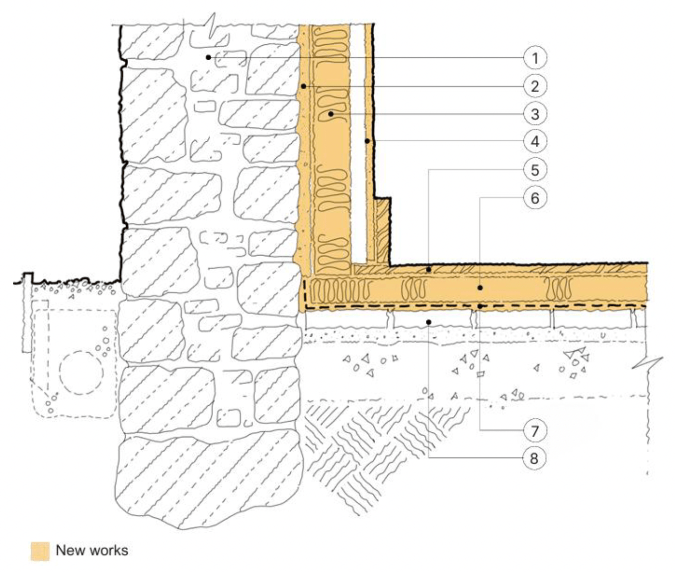
Drawings notes:
1. Existing solid masonry wall.
2. Existing internal plaster removed (could be left in place subject to providing sufficient key).
3. New, applied insulation board. Either direct to wall or over intermediary plaster coat. Insulation should be vapour permeable, capillary active and hygroscopic to ensure moisture can evaporate into cavity / room.
4. Service void and new wall finish (e.g. decorated plasterboard).
5. New ‘floating’ floor finish suitable for the purpose over insulation.
6. Thin, high performance rigid insulation suitable for flooring laid over DPM.
7. DPM laid over existing floor and taped/sealed to perimeter walls.
8. Existing floor finish (e.g. tiles on concrete slab) left in situ.
Note:
- Insulation board (should be returned into all door and window reveals).
- Insulation should tightly butt up against floor insulation (no gaps) and be taped at junction.
The existing solid floor shown here has a surface with no historic interest which has been overlaid with insulation and a new floor finish. It also shows a solid wall where the internal plaster has been overlaid with new insulation, a service void and new internal wall finish. Note that it is usually difficult to raise the floor levels as shown because of the impact this has on adjacent floor levels, accessibility, stairs, internal doors and so on. However, it is a relatively simple and cost-effective solution where these issues can be resolved.
In this case, a DPM has been added, whereas it may be considered that the existing tiles and concrete slab already effectively acts as a DPM (or that there is one known to be below the slab). Note that this changes the conditions of the wall base but that that this illustration incorporates new land drainage externally to reduce potential upwards groundwater pressure.
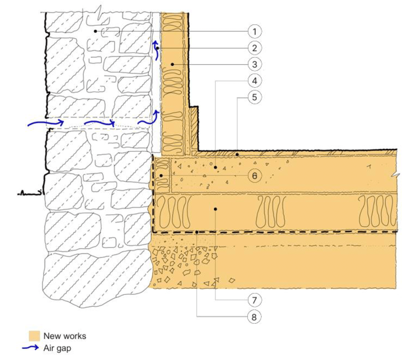
Drawings notes:
1. Existing solid masonry wall.
2. Existing internal finishes removed, treated battens applied to masonry surface to form cavity.
3. New, applied insulation board with adhered plasterboard, or similar finish, installed tight to perimeter insulation below (e.g. remove any concrete from slab pour over perimeter insulation).
4. Concrete slab or screed installed, with reinforcement as necessary to suit new floor finish.
5. Existing floor (e.g. concrete slab and floor finish) removed and possible excavation to create adequate depth.
6. Perimeter insulation installed wide enough to overlap with wall insulation - creates continuous insulation layer across the junction - sealed to insulation below.
7. Rigid insulation suitable for being laid beneath slabs. All joins to be taped, no gaps and tight up against perimeter walls.
8. DPM laid over undisturbed ground (may require protection e.g. sand or fleece) and taped/sealed to perimeter walls.
Note:
- Cavity may require to be vented, ensure potential moisture issues are resolved to satisfaction of a specialist or Building Control
- No DPC required in wall, but external ground level should be below internal floor level or some other mechanism in place to avoid moisture rising within the wall. Note accessibility at entrance doors should also be borne in mind.
This illustration does not represent best conservation practice but shows a common situation where there may not be a better technical approach to bringing a space back into use. This compromise may be appropriate where the space contains no finishes of obvious architectural or historic interest or unsuitable existing finishes are to be removed, and/or where modern finishes internally are required. In detail, existing wall and floor finishes have been removed and replaced with modern materials.
In circumstances where this detail is used, it is important that the designer demonstrates to the verifier how the cavity will be ventilated and any residual organic materials with the wall (such as timber lintels or floor joists) are to be protected from moisture in the long term. Vents in the masonry at low and high level as shown provide an example of this.
With the use of a DPM, it is also important that the designer demonstrates how the walls are to be protected from rising damp. In relation to thermal performance, note that it is important that the perimeter insulation is fully contiguous with both the floor insulation below, and the wall insulation above to avoid a thermal bridge.
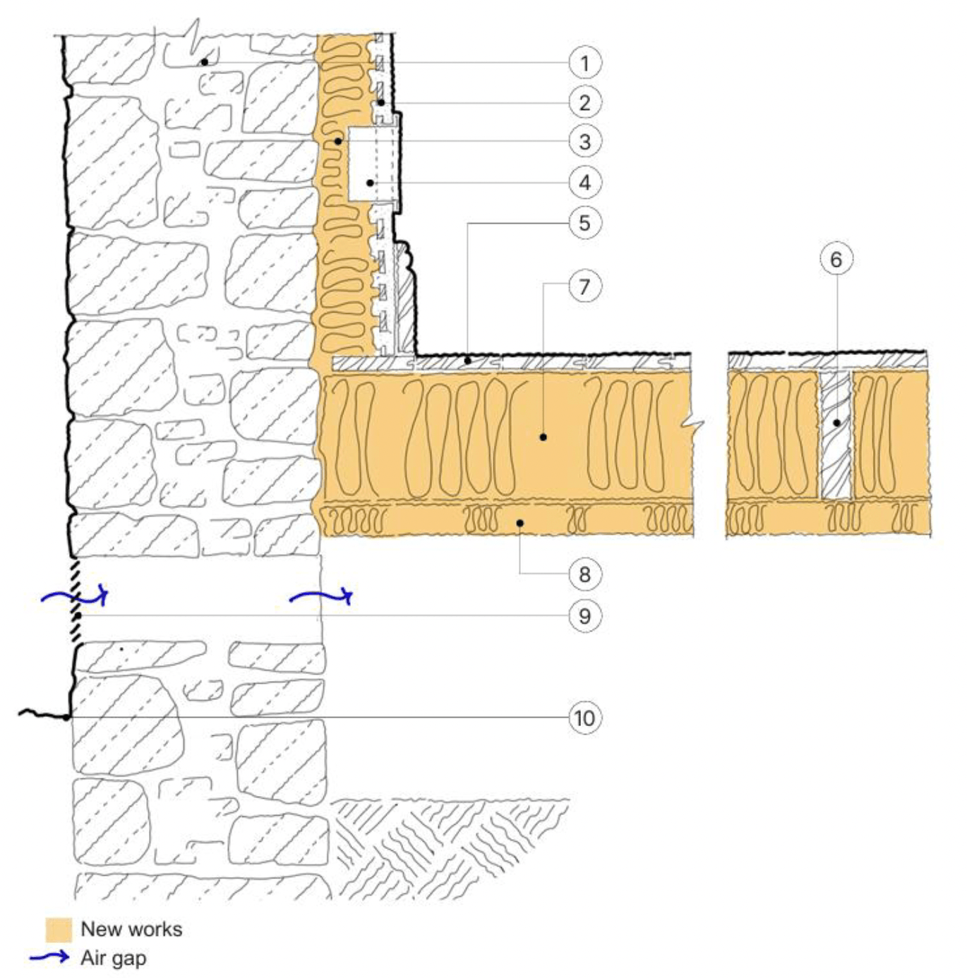
Drawing notes:
1. Existing solid masonry wall.
2. Existing internal lath and plaster (or similar) over a cavity.
3. Insulation injected through holes in the lath and plaster to fill the cavity behind with insulation. Existing penetrations (such as socket and switch boxes) may be used for injection, but new holes will also be required. The contractor should ensure that insulation does not spill into flues, vents, gaps above and below, all gas appliances work unimpeded etc. Use thermography or borescopes to check installation if possible.
4. Water pipework should be insulated whereas electric cables should be within conduit or below insulation. Consider future access for all services.
5. Existing floor finish considered significant, where access is available to the solum.
6. Check existing joists are dry and sound.
7. ‘Soft’ or ‘semi-rigid’ vapour permeable and hygroscopic insulation installed between joists, with no gaps, to the full depth to maximise thermal performance.
8. Rigid or semi-rigid insulation board to support insulation above, fixed to underside of joists. Must be vapour permeable and hygroscopic to ensure vapour dissipation into ventilated solum below.
9. Ensure wall vents are not deliberately sealed, or covered by debris, leaves, ground levels rising over time, new ground finishes. Ensure adequate ventilation to perimeter and through solum (i.e. through internal partitions).
10. External ground level reduced to ensure clear air path through air bricks.
Note:
- Even if the floor finish is not considered significant, installing insulation from below is likely to be a simpler and more effective solution (than removing boards and installing from above) as long as there is sufficient access.
This shows a suspended timber floor with an undisturbed floor finish. It also shows a solid wall, with relatively undisturbed internal lath and plaster finish that has been insulated by injecting insulation between it and the masonry wall behind.
Because of the lack of damage and disruption to both wall and floor finishes, this provides an effective solution where the finishes clearly contribute to a building’s architectural or historic interest but is equally useful for any similar arrangement. In the floor, this is achieved because access to the solum is relatively easy. Typically, access is manageable in solum depths of 600mm or more, but access is needed from hatches in the floor finish, or via other parts of the solum. Note that an additional layer of insulation is shown beneath the joists. A membrane or netting could be used, but this solution provides additional insulation and reduces the thermal bridging effect of the joists.
A DPC is not required in the outer wall but note that it is important to check the condition of the timber joists as these are shown embedded within the masonry wall, so it is important that this wall remains dry. There are several issues relating to the wall detail which are discussed in 6.2.3 above. It is also documented fully in Historic Environment Scotland’s Guide to Energy Retrofit of Traditional Buildings.
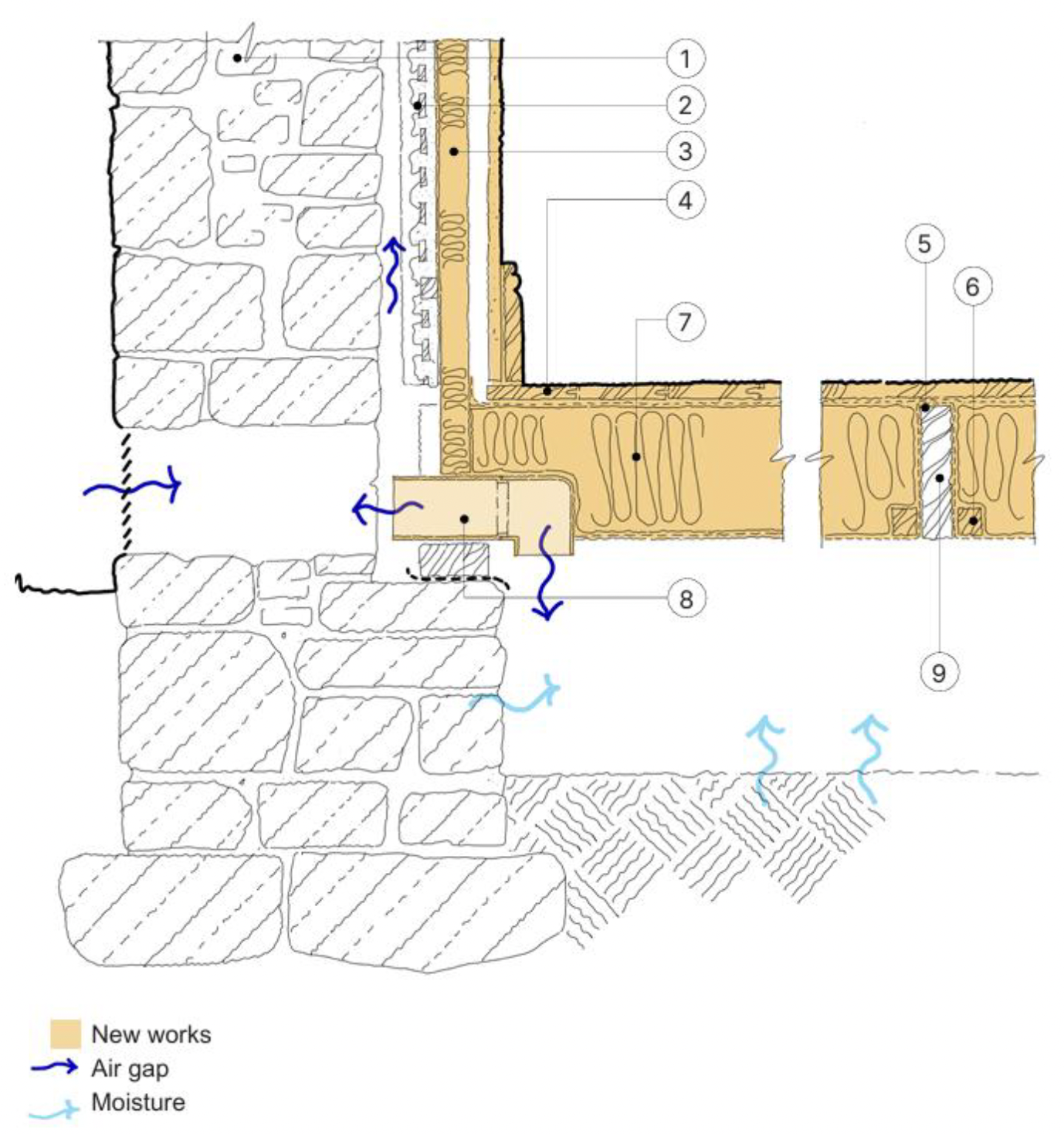
Drawing notes:
1. Existing solid masonry wall.
2. Existing internal lath and plaster (or similar) over a cavity, undisturbed.
3. Insulation as rigid or semi-rigid boards affixed to existing wall finish, no gaps, with service void over and plasterboard or similar finishing. Ideally insulation boards should extend down between floor joists to form a tight and complete boundary, sealed to joists.
4. Existing floor finish removed for works and later reinstated. Care needed with access and unbraced joists.
5. Install VCL across top of joists, taping to wall insulation layer to ensure contiguous airtightness, before installing new floor finish.
6. Dress breather membrane or netting over joists and affix to bottom edges on both sides with battens to ensure insulation fully fills all areas without ‘lifting’ away from joists.
7. Fully fill space between joists with quilt-type vapour permeable and hygroscopic insulation, no gaps. Ensure insulation is neatly fitted around vent.
8. Location of air bricks within joist depth means a periscope vent or similar is needed to direct air to the solum while allowing floor joists depth to be fully insulated. Ensure vent is robustly fixed and sealed to membrane.
9. Check existing joists are dry and sound.
Note:
- Cavity may require to be vented, ensure potential moisture issues are resolved to satisfaction of a specialist or Building Control
- Water pipework should be within conduit or kept below insulation. Consider future access for all services
This shows a suspended timber floor with the boards removed to access between joists for insulation as there is no access from below. It also shows a solid wall, with internal lath and plaster finish left in place and over which has been installed new insulation and a service void with new plasterboard or similar finish. Air movement behind the existing lath and plaster is unaffected.
The drawing shows the insulation taken down over the joists to provide a robust ‘edge’ against which softer insulation within the floor can be taken but the key is that the insulation from floor and wall meet, ideally with airtightness also achieved as shown. The wall insulation could also be within a timber frame, but this creates thermal bridges at the timber and makes the extension down across the joists more difficult.
In this example the air bricks are at joist level, so a periscope vent is needed to ensure the solum remains fully vented. As the solum depth here is limited it may be helpful to clear the solum of debris to maximise the free air path across the space.
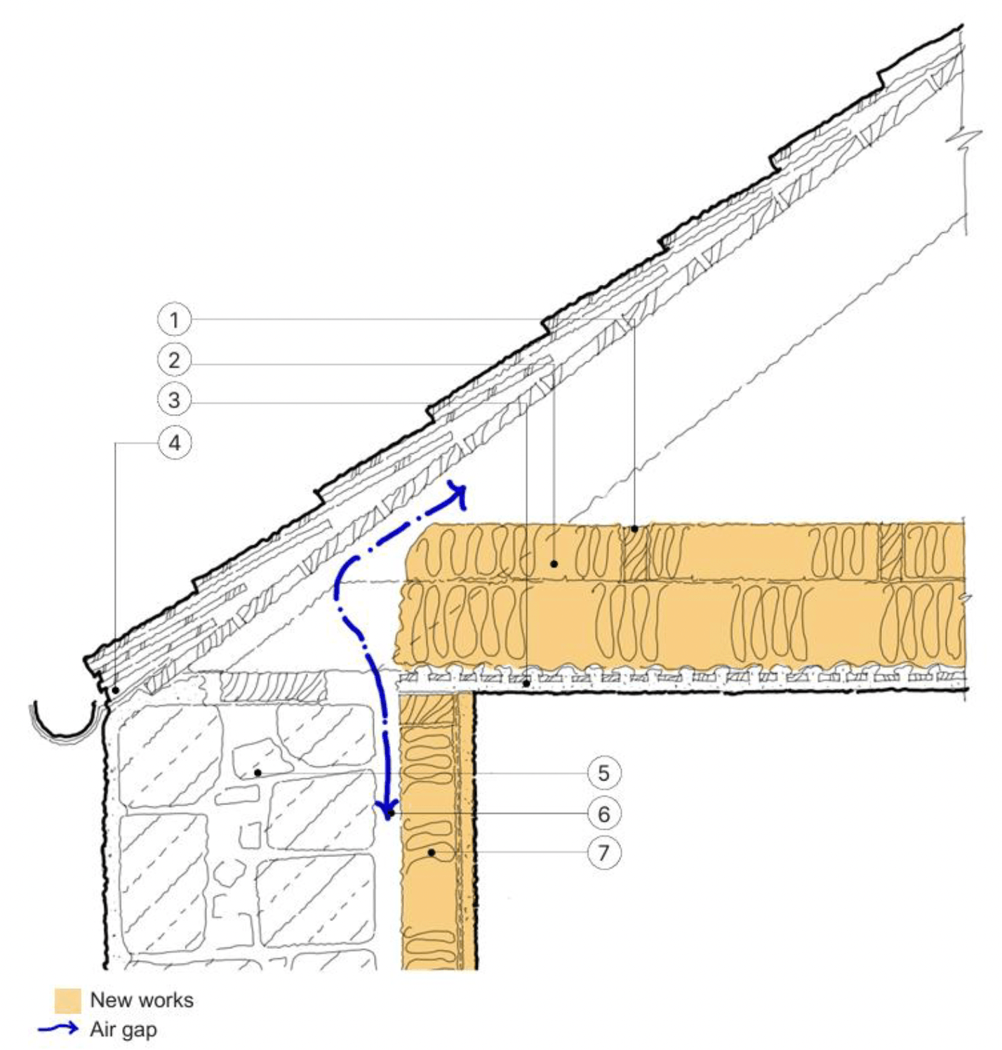
Drawing notes:
1. Potential addition of joists to form raised structure if access deck required.
2. Insulation fitted between ceiling joists, without gaps. Insulation should extend slightly beyond internal wall insulation, if possible, to minimise thermal bridge. Air path at wall head to be maintained.
3. Existing lath and plaster ceiling finish retained but note check perimeter gap left if needed for air movement.
4. This detail shows mortar at eaves blocking ventilation. Traditional roofs often had no formal ventilation at eaves, while widespread air leakage meant roof areas were sufficiently ventilated. In this case, insulation has been added meaning clarity is required as to routes of ventilation to achieve similar levels of protection.
5. Existing solid masonry wall.
6. Maintain air movement within cavity. Ensure existing ceiling finish does not block air movement from wall cavity to attic. If ventilation is possible at eaves, then wall cavity ventilation may not be required.
7. Existing linings removed and new internal wall insulation system installed. This is to be formed with VCL and plasterboard internal finish.
This shows a ‘cold roof’ where the insulation has been laid within and above the ceiling joists, making the remainder of the attic and the roof layer itself ‘cold’. The wall has had its existing linings removed and a new internal insulation system installed with a vented cavity and insulation within a timber frame.
Although this is a common detail, the timber frame itself represents a thermal bridge where the top runner abuts the existing ceiling, making this corner a potential condensation and mould risk. A better alternative might involve additional insulation over the timber frame, or a continuous insulation layer as shown in illustration 91.
Care would be needed with any penetration in the wall insulation which could introduce a thermal bridge and a break in the VCL. The same is true with any recessed lights, for example, which should be carefully covered with fireproof hoods and insulation carefully fitted around. If air movement is required from the wall cavity, ensure that neither the existing plaster ceiling nor its insulation blocks the gap at the wellhead. However, the insulation should still overlap as far as possible to reduce any thermal bridging here.
It is likely that the verifier will consider the new plasterboard and existing plaster layers as being adequate to prevent fire spread into the cavity and into the attic. It may be that an intumescent caulk seal at the corner would improve the detail, but in some cases verifiers may want to see intumescent strips within the cavity. It is important to ensure this is resolved with them in each case.
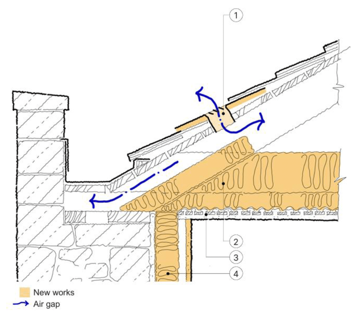
Drawing notes:
1. In-line slate vent shown providing ventilation to attic space in lieu of reliable eaves or wall cavity ventilation.
2. Insulation fitted between ceiling joists, without gaps. Insulation to extend over wall insulation. Insulation laid cross-ways above to achieve required U-value (no maintenance access required).
3. Existing lath and plaster ceiling finish retained.
4. Existing solid masonry wall and new internal insulation, per illustration 90.
Note:
- The ceiling finish may need to be cut back to allow the wall insulation to directly abut the ceiling insulation above and avoid a thermal bridge.
- This illustration shows typical parapet details where there is no possibility of eaves ventilation and in this case, no air route from the walls. However, fresh air is required to circulate around the wallhead, rafter ends and parapet gutter joinery.
This shows a ‘cold roof ’ as above with a parapet which prevents eaves ventilation and increases the risk of water damage to the wallhead. The wall insulation is as per illustration 90 but note in this case the existing ceiling lath and plaster has been cut back to ensure that the wall insulation meets the ceiling insulation above.
In a situation like this, it is recommended that efforts are made to inspect the wallhead and parapet joinery to make sure conditions are sound and dry. If slate vents need to be installed (as shown) this could be combined with a general review of the wallhead joinery and some of the insulation shown could be installed from the outside.
Without ventilation from the eaves or wall, the slate vents have been inserted (as low as practicable) and a clear path formed to allow for fresh air to circulate around the wallhead joinery, although this is not ‘thru’ ventilation which would be ideal.
In some cases, the verifier may require a cavity barrier at the wall / roof junction to guard against fire spread. Reference should be made to Section 2 (Fire) for guidance.
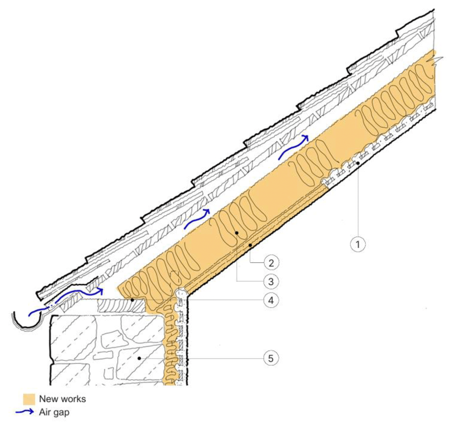
Drawing notes:
1. Existing lath and plaster finish retained, a section cut out to access wallhead.
2. Once insulation is installed, install plasterboard (two layers or thicker board may be needed) flush with adjacent finish.
3. Using access strip, install insulation between rafters ensuring minimum 50mm air gap is maintained between eaves and attic or ridge ventilation.
4. Access from above to inspect condition of rafter ends and wallhead joinery, install quilt-type insulation as shown.
5. Existing solid masonry wall and new internal insulation, per illustration 92 Note the need to contain insulation at wallhead.
This shows a warm roof where the insulation has been laid within the rafters, keeping (part of) the roof structure warm. The wall has a retained lath and plaster finish and has insulation installed behind, referring to illustration 92 for more on the wall detailing.
In this case, there is no air movement from the wall, but eaves ventilation is reliable and can be used to ensure any moisture within the roof structure is safely vented away. The gap should be at least 10mm continuously (or as required by BS 5250: 2021) and in practice mesh would be required to resist insect or bird ingress at the eaves as shown. Care has been taken to ensure continuity of insulation.
Inserting insulation between rafters can be difficult as there is often no access from above or below and so access can only be gained by removing all or part of the internal finishes. This illustration shows a partial removal of internal finishes to facilitate the insulation installation and check on the condition of the wallhead and rafter ends without removing all the finishes.
In some cases, access is available from above or below, for example in some ‘room-in-the-roof’ arrangements meaning that the internal finishes can be left in situ. Note that while rigid insulation boards can be easier to insert between rafters, being more robust, any gaps between imperfectly fitted board will lose heat, and in practice, a tightly fitting board, e.g. a ‘semi-rigid’ board that can be cut tight and squeezed to form a snug fit may be more effective in practice.
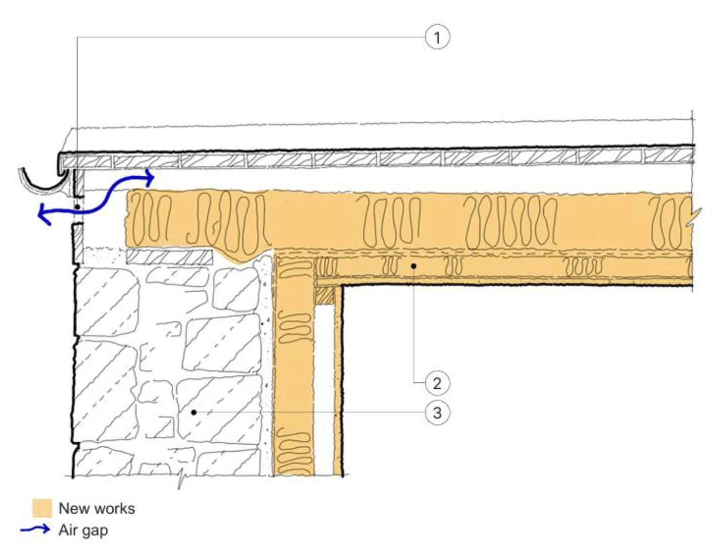
Drawing notes:
1. Ventilation holes formed in the verge boarding to ensure ventilation to roof joinery is reliable, note these have been inserted beneath gutter for minimum visual impact.
2. Ceiling finish has been removed, insulation inserted between joists, vapour control layer fixed across underside of joists (and sealed to wall before installation of insulation) with insulated plasterboard or similar installed after.
3. Existing solid masonry wall and new internal insulation, per illustration 92.
Note: Service void has been created in the walls with all services assumed to be contained there, rather than compromising insulation levels in ceiling, and which does not have a ceiling void.
This shows a flat roof where the roof finish is retained, and ceiling has been removed to lay insulation within and below the rafters. The wall has been insulated in the same way as illustration 90.
This solution would only be adopted where the ceiling finish is not considered to be significant or contribute to the architectural or historic interest of the building.
It also shows a situation where existing ventilation to the roof void did not previously exist so extra precautions have been taken to protect roof joinery from moisture. Ventilation holes have been formed in the verge boarding to ensure ventilation to roof joinery is reliable. Note that these have been inserted beneath gutter for minimum visual impact.
To minimise risk to the roof structure from moisture, the ceiling finish has been removed, insulation inserted between joists, a vapour control layer fixed across underside of joists (and sealed to wall before installation of insulation), with insulated plasterboard or similar installed after. Note that it is important not to penetrate this vapour control layer, for example via cables to a ceiling lamp. Air and vapour tight grommets can be used where cables are required.
In some cases, the verifier may require a cavity barrier at the wall / roof junction to guard against fire spread. Reference should be made to Section 2 (Fire) for guidance.
b) Externally applied wall insulation
As noted in Section 6.2.3, externally applied insulation (EWI) is unlikely to be adopted in many situations because it often makes a significant change to the appearance of a building and there are several practical challenges associated with its application. However, where its application is feasible it has several advantages over internally applied insulation.
Practical recommendations for EWI are best described as a list rather than a detail and are as follows:
Preparatory Issues:
- Review all utility routes and penetrations. Some may enter through the floor, but where they enter through the wall, these may best be moved, or bespoke details created to avoid areas of weakness and thermal bridges. Externally mounted gas boxes can be a particular problem and should ideally be moved (by the utility company) to allow insulation boards to be inserted behind, but this can be difficult to co-ordinate.
- The external condition of the wall should be assessed and any structural defects, including boss or cracked render need to be addressed so that subsequent fixings into the wall are not at risk.
- Downpipes and waste pipes need to be moved outwards and fixed back with special fixings that extend through the insulation whilst remaining robust. Details may be required at top and bottom to re-connect with the gutters above or drains below. This work is not usually covered by grants for EWI work and so is sometimes overlooked, leaving both unsightly arrangements and a long-term condensation and mould risk internally.
- Existing eaves and verges may need to be extended to effectively cover the increased depth of wall. Proprietary cover flashings which extend beyond eaves and verges are unlikely to be visually acceptable or sufficiently robust. Wall insulation needs to meet the roof insulation where possible and this too can necessitate extensive alterations at eaves level to avoid thermal bridging whilst maintaining ventilation to the roof.
- EWI should extend downwards at least as far as an overlap of the depth of the ground floor, but ideally as far as possible without disrupting the wall foundations. This is to reduce the thermal bridge at the base of the wall. The insulation at and below ground level should be of a closed cell type to avoid deterioration and can be set back to mimic a standard plinth detail.
- Where there are suspended floors, ventilation should be maintained to the solum, which may require extending air bricks or other vents.
- Detailing around windows and doors needs to be carefully managed. Reveals should be insulated to avoid thermal bridging. It is also important that suitable sills or overfills are provided which mimic the previous detailing to create a robust watertight detail at both ends of the sill, as well as a suitable drip.
- Any external fixings will need to be moved and re-attached, often necessitating more complex fixing details. Examples include external lighting, signage, satellite dishes and aerials. All fixings should be thermally broken where possible.
- Some services run across the surface of the walls (e.g. telecom cables) and where these cannot be re-routed they should be run within conduits and embedded in the system, minimising the loss of insulation depth in preference to being fixed to the external face of the finished elevation.
Design and installation:
- It is crucial that the overall system (including render finish) is both weathertight and vapour permeable so that wind-driven rain cannot enter, while any moisture within can dissipate naturally.
- Insulated renders tend to be used less in retrofit because of the relatively modest U-value improvements they can offer. However, in many cases, these may provide a more suitable solution for some traditional buildings where they are (visually) a like-for-like replacement for existing render.
- Insulation boards in conventional systems should always be fixed without any gaps between boards, or between boards and the masonry substrate. The arrangements, beading and fixing patterns should be specified by the manufacturer or supplier. All other requirements of the manufacturers should be followed (in relation to fire compartmentation for example).
- Original features of the elevation of the building should be replaced or re-created wherever possible.
c) Windows and doors
Window openings and frames are a significant part of the character of a building’s elevations and there should be a presumption against altering their proportions or design.
As a rule, traditional windows should be retained and repaired as part of the conversion process and other means employed to improve their efficiency. Where new openings must be formed, these should generally match the proportion, materials and design of the existing windows.
Where historic glass has been largely or wholly replaced in the past, and/or the timberwork is clearly beyond economic repair, there may be scope for part or wholesale replacement of the window. This would be agreed with the planning authority in the context of local and national guidance on windows in protected buildings.
In all cases the use of the word ‘window’ refers to both windows and doors. Issues affecting the various measures noted below are discussed in the previous section 6.2.3.
In buildings of the highest cultural significance, where both the window timbers and glass must be retained, the following options may still be available to improve energy efficiency of the window.
- Draught-stripping between and around casements.
- Draught-stripping and insulation works between the window and the surrounding masonry, although the latter will require removal and replacement of surrounding joinery.
- Secondary glazing (which itself may be double glazed), where its design and construction would be unobtrusive and will not reduce functionality (opening for ventilation, cleaning and maintenance).
- Use of existing shutters, which can be draught-stripped and insulated to enhance their capacity to reduce heat loss at night.
- Use of insulating or reflective blinds to reduce heat loss at night, where their use would not detract from the appearance of the window, the wider building or any important decorative schemes within it.
- Use of lined and insulating curtains to reduce heat loss at night.
In other cases of cultural significance, where the window joinery may not be changed, but there is more latitude regarding the glass itself, and in addition to the options above, it may also be possible to:
- Replace existing single panes of glass with thin, but high performing double glazed or vacuum panes.
Where it is permissible to replace windows, or where inappropriate modern windows are themselves to be replaced, the following should be considered:
- The proportion of the window overall, position of glazing bars and number of panes etc. should match the existing or original window layout as far as possible.
- It is important to match the dimensions of the historic timbers as closely as possible, including the thickness of glazing bars and sash frames.
- The opening arrangement should match the original wherever possible but there may be cases where this has to be considered in the context of modern requirements for fire escape and security.
- In a modern double or triple glazed window, the weakest link thermally will normally be the frame, rather than the glass. For this reason, it is worth investigating thermally efficient frames as well as glazing panes, with attention also paid to warm edge spacers which seal the glazing panes
- The air leakage performance and method of installing the window (i.e. detailing of the junction between the window and the wall) are as important as the U-value of the window in terms of thermal performance.
- Because window reveals are the thinner parts of any external wall, the installation of new windows offers a good opportunity to improve the insulation of reveals along with the window itself.
Contact
Email: buildingstandards@gov.scot