
Conversion of traditional buildings: guidance
This guidance provides a technical insight into the conversion of Scotland’s traditional buildings, balancing building regulation compliance with conservation. It promotes a holistic, risk-based approach to technical compliance in the performance of traditional buildings.
Part of

3.15 Condensation
Mandatory Standard
Standard 3.15
Every building must be designed and constructed in such a way that there will not be a threat to the building or the health of the occupants as a result of moisture caused by surface or interstitial condensation.
3.15.1 Application of standard to conversions
in the case of conversions, as specified in regulation 4, the building as converted must be improved to as close to the requirement of that standard as is reasonably practicable, and in no case be worse than before the conversions (regulation 12, schedule 6).
3.15.2 Commentary
The risk of damage from condensation can be an issue for all traditionally constructed buildings. This standard contains no specific controls but instead, generalised objectives and directs the reader to guidance in BS 5250: 2021 Code of Practice for the control of condensation in buildings. Additional sources of guidance on this area are included in 3.15.5.
BS 5250: 2021 includes guidance specific to existing buildings and the additional documents listed in 3.15.5 provide advice on details meeting the building standards. All documents provide guidance on the important principles that must also be observed in the conversion of traditional buildings, as well as general best practice approaches to managing moisture.
The risk of condensation occurring at any point in a construction is determined by the differences between the internal and external temperature and vapour pressure, the materials which make up the building envelope (including any cavities) and the relative positions of those materials.
Moisture safe design cannot be separated from other design issues and regulatory requirements but needs to be balanced against other key design aims and be part of an on-going discussion and feedback process throughout a building project.
It is essential to establish the correct process for moisture risk assessment, design and management. Taking the Whole Building approach is fundamental for the successful management of condensation in traditional buildings. New buildings utilise thermal isolation (avoidance of cold bridging), vapour control (vapour checks, vapour barriers and breather membranes) and extraction (mechanical ventilation in bathrooms and kitchens). Whilst is it possible to use some of these methods to manage condensation in the conversion of traditional buildings, the design must be sensitive to their cultural significance and recognise the need for compatible materials. The approach must also consider that traditional construction-controlled condensation through a greater reliance on natural ventilation and heating from open fires.
The alteration of any element of a building can lead to unintended consequences and increase risk of condensation. All retrofit of buildings increases moisture risk and, coupled with increased flood risk, rainfall and relative humidity due to climate change appropriate action should be taken to mitigate this as far as possible. Typical traditional construction combines ventilated timber floors, lath and plaster walls with air spaces behind, uninsulated freely ventilated roofs, single glazed windows and open fires in every apartment. This detailing is an effective method of reducing condensation risk but it often under performs against modern thermal standards and would not meet the building standards energy requirements outlined in Section 6.
Caution should be used when adding vapour membranes or barriers where none existed previously, particularly where the aim is to increase insulation and/or airtightness in a conversion. Airtightness can be achieved in traditional construction by combining building standard compliant targeted ventilation in kitchen and bathrooms with measures such as draught-stripping and flexible closing of hearths.
Well applied and detailed lime plaster and render finishes can also increase air tightness whilst increasing moisture buffering capabilities of a building. This is particularly useful in flood zones where insulation or vapour barriers are unlikely to be an effective and sustainable long-term solution. Lime plaster and renders can aid drying of traditional construction and in their resilience to condensation, flooding and higher rainfall.
Traditional slated roofs generally did not include felt membranes under the slates, which were nailed directly to gap-boarded sarking, and, as a result, allowed air to penetrate freely into the roof space. Alteration to these details without careful thought can have serious unintended consequences and lead to increased condensation levels. Therefore, attention should be paid to retaining ventilation gaps and pathways where these are essential to the long-term health of the building.
a) The Whole Building Approach
Moisture safe design is required to meet this standard and therefore cannot be separated from other design concerns and regulatory requirements. A balance must be struck with all design aims within a project to ensure ongoing feedback and the correct processes for moisture risk assessment, design and management are in place.
The whole-building approach is a systematic process accounting for interactions between fabric, services and occupants. This assessment is made in the context of the building’s geographical location, its history, the type of occupancy and any future changes that might be proposed for it. This approach is based upon the principles outlined below and should be supplemented using prescriptive guidance and modelling where these are appropriate and useful.
The whole-building approach follows these main principles:
i. Understand the context of the building, the building project and ensure the design is compatible with this context. The traditional materials and construction methods used in older buildings have evolved to be compatible with the local climate. When working on existing buildings, an understanding of these materials and construction methods is essential prior to the design of a conversion scheme.
ii. Understand and avoid harm to cultural significance.
iii. Ensure coherence in approach and detailing.
iv. Build in extra capacity in the design and construction phase for uncertainties in the build process and future challenges.
v. Ensure that caution is taken in the use, maintenance and after-care phase where there are ongoing requirements of care and uncertainty of outcomes.
b) Thermal bridging
Thermal bridging occurs where the continuity of the building fabric is interrupted by an element that allows significantly greater heat loss than the surrounding construction. These thermal bridges commonly occur around openings such as lintels, jambs and sills, as well as at wall-to-roof junctions, wall-to-floor junctions, and where internal walls penetrate the external envelope.
Thermal bridges create a direct pathway for heat to escape to the outside, resulting in heat losses that are disproportionate to their size. This can reduce the overall thermal performance of the building and may lead to surface condensation on internal walls, potentially causing damage to the property and posing a risk to occupants' health.
Typical situations where surface condensation, interstitial condensation and moulds may occur include:
- window and cupboard recesses,
- on and below window sills,
- external door threshold areas,
- lintels (timber safe-lintels are at particular risk),
- uninsulated floor wall junctions,
- junction of insulated roof with poorly-insulated walls.
It is important to understand that thermal bridging can be effectively managed by ensuring continuity of insulation. Practitioners should decide if it is better to retain and maintain existing finishes because they are performing well or introduce insulation with a limited thickness which can ensure a continuous thermal layer while being more sympathetic to the building and its detailing.
c) Assessing the likelihood of condensation
BS 5250: 2021 provides three main ways that moisture risk can be assessed and managed:
- By understanding and applying the principles of moisture safety in buildings, namely the whole building approach. This approach is used where there is uncertainty regarding experience, data and parameters or modelling methods and protocols. This is the most suitable approach for traditional and culturally significant buildings.
- By prescriptive guidance. This is based on the experience of commonly used applications where there is good evidence of success over many years; for example, the guidance given for ventilation of ‘cold’ pitched roofs. This guidance is used where there is certainty of experience, sufficient data and empirical testing to provide guidelines for practice and design to prevent moisture risk. Prescriptive guidance is provided as recommendations which form the provisions of this standard.
- By modelling, where appropriate, in accordance with standards such as BS EN ISO 13788 or BS EN 15026; also, BS EN ISO 10211 for thermal bridging risk. This form of guidance is used where there is uncertainty with regard to experience or context, but sufficient certainty of data, moisture mechanisms and safety parameters.
d) External Condensation Risk
The following text is adapted from BS 5250, section 4.4 External climate (condensation risk). Designers should assess and document the factors likely to affect the formation and persistence of condensation in buildings, including exposure to sunlight, clear night skies, wind and driving rain. The potential effects of these are as follows.
i. Solar gain. The external surface temperature of roofs and walls can be increased by direct sunlight to several degrees above the external air temperature, even in winter. This can promote rapid drying of condensation which has occurred within the structure and may create moisture gradients within the fabric. There are further provisions outlined in BS 5250 regarding condensation risk management in roofs that span greater lengths. These details emphasise the need for enhanced ventilation strategies and highlight specific measures to address moisture buildup effectively in such scenarios. It can also drive moisture towards the interior of the building where it might condense on any air and vapour control layer (AVCL) or cooler internal surfaces. The degree of exposure to direct sunlight can be affected by neighbouring buildings, structures and/or trees.
ii. Night sky radiation. On clear still nights at any time of year the radiative temperature of the sky is much less than the external air temperature. This can rapidly cool the external surfaces of roofs and walls overnight, meaning interstitial condensation can occur on the inside of an external weatherproof layer. Although this might evaporate rapidly the next day, there can be sufficient accumulation of condensate to cause running or dripping overnight.
iii. Exposed positions. High wind speeds, especially when accompanied by precipitation, chill the external surfaces of the building, thereby significantly increasing the risk of interstitial condensation within the structure.
e) Condensation and the risk of mould growth.
In dealing with condensation, it is also important to recognise the role of mould growth. This standard covers the threat to the health of occupants; mould spores may affect health, especially of persons suffering from asthma or allergies. While surface condensation will occur when the surface temperature falls below the dew-point temperature of the ambient air, mould growth can occur on a surface that is above dew-point temperature. Mould growth requires moderate temperature, abundant nutrients and adequate moisture. Mould thrives within the same temperature range at which we like to keep our homes, and the indoor environment provides abundant nutrients for growth.
Removing mould from buildings completely is not possible as mould spores are an abundant part of natural world. However, managing moisture so it is not excessive in the air and on surfaces is the most effective way to inhibit growth. Introducing insulation does not in itself reduce mould risk. Whilst it can help to increase internal surface temperatures and reduce heat loss, it also increases risk of thermal bridging and interstitial condensation where a building has been poorly detailed.
Practitioners should also be aware of the risk associated with the introduction of construction moisture during building works and that mould growth can be mitigated from the outset with improved construction practice. Adequate drying times for new works, proper protections during work and ensuring materials are not damp at installation all contribute to managing moisture and reducing the risk of mould growth.
Mould risk should be managed through balancing internal moisture with adequate heating, consistent and sufficient ventilation, preventing water ingress and reducing extra moisture. Further information on mould and manging risk can be found at the UK Centre for Moisture in Buildings.
BS 5250: 2021 states that for the assessment of designs for which calculations are required, designers should assess the risk of surface condensation, mould growth and interstitial condensation using the methods described in BS EN ISO 13788 or BS EN 15026 and/or BS EN ISO 10211 (according to context, with reference to Clause 13).
3.15.3 Issues to be considered
Typical risks in the conversion of historic/traditional buildings
1. Condensation in roofs
- The addition of insulation in roof space increases risk of condensation.
- Lack of ventilation can lead to increased risk of condensation in roof spaces and consequential problems of timber decay and mould growth.
- Condensation on slate fixing nails can lead to corrosion and failure.
- Installation of roof ventilators can affect the appearance and character of the roof although there are many available products that have been designed to be sensitive to culturally significant buildings.
- Installation of impermeable roofing felt during previous remedial works can severely restrict the level of incidental/beneficial ventilation within the roof space, requiring the provision of roof vents. The impermeability of the ply layer can also trap moisture at its underside where it is in contact with the timber sarking.
- Provision of a vented cavity in flat roofs may require removal of historic finishes and/or raise the level of the roof line.
- Lead corrosion can occur to the underside of existing and new lead roofing.
- Use of inappropriate membranes beneath leadwork can inhibit moisture movement and accelerate lead corrosion.
2. Surface condensation and thermal bridging
- Where moisture vapour meets a cold surface, it will condense,
forming surface condensation. Failure to achieve continuity of insulation at the junctions of the roof and the wall could result in cold zones on the wall and/or ceiling leading to surface condensation.
- Detailing of junctions to avoid the introduction of a thermal bridge in traditional buildings can be complex due to the presence of architectural detail such as original cornices, ornate plaster ceilings and architraves.
Condensation associated with single glazed windows and window jambs:
- Replacement double glazed windows may have an impact on the cultural significance of a building and cause condensation to move elsewhere.
- Secondary glazing has been demonstrated to be a good option for improving the thermal performance of windows in locations where the cultural significance of the existing windows requires their retention. In the context of a listed building, care should be taken to ensure the design and fitting of secondary glazing is sensitive to the significance of the interiors and existing fabric. In all traditional buildings, the specification of the secondary glazing should ensure appropriate ventilation of the building is maintained, and that the glazing unit is well detailed with the window reveal to prevent heat loss and cold bridging.
- Both internal and external shutters have been shown to be beneficial in the management of condensation, solar gain. and storm resilience. Where there is historic precedent or appropriate need, shutters may form a traditional technical and high performing adaptation.
- Condensation on windows and jambs can cause decay in window timberwork and damage to internal finishes on walls and floors.
Condensation on walls and fitments in areas of high humidity:
- To meet the standard, ventilation is required in bathrooms and kitchens. However, even with good ventilation, areas such as cisterns and tiles can have high temperature differential leading to surface condensation and deterioration of both finishes and historic fabric.
- Mechanical ventilator locations and their proliferation can be visually intrusive to historic or traditional buildings if handled insensitively.
3. Interstitial condensation
- Where interstitial condensation forms within the fabric of a traditional wall construction, it will have the most severe impact where construction timbers are built into the external stone wall.
- Surface condensation can have a detrimental impact on timbers built into walls leading to damage and decay.
- Timber lintels and joist ends are liable to absorb any condensation forming on and tracking down the inner face of the outer stone leaf.
- Care is required to interpret correctly the source of moisture and ensure that moisture from poor maintenance (pointing, rainwater gutters etc.) is not confused with interstitial condensation.
- Incomplete thermal insulation and vapour checks, e.g. at windowsills and window returns, may encourage interstitial condensation on colder surfaces.
In accordance with BS 5250, the span and pitch of a roof play a critical role in determining an appropriate ventilation strategy to mitigate the risk of interstitial condensation effectively. When assessing the risk of interstitial condensation occurring within a cold roof, designers should take into account the following inter-related factors:
- The internal vapour pressure (which depends upon moisture generation and the degree of ventilation in the occupied spaces).
- The rate at which air and water vapour are transferred by air leakage and diffusion from the occupied spaces into the roof build-up (determined by the airtightness and vapour resistance of the ceiling).
- The rate at which water vapour is transported from the ventilation space to outside (determined by the degree of ventilation of the ventilation space).
4. External climate
Due to Climate Change factors, we are seeing greater extremes in our weather, including storm events, temperature extremes as well as milder, more humid winters.
Larger volumes of driving rain are likely to increase the number and severity of moisture problems.
External detailing is key to managing water penetration, solar gain and night sky radiation. Rapid heating and cooling of external surfaces can lead to condensation and material decay. Attention should be given to the detailing of all elevations, not just those most affected by the prevailing weather.
Retention or addition of traditional detailing such as slate hanging and deep eaves should be considered to improve the resilience of a building and manage moisture. BS 5250 states that “Vernacular building design specific to an area is often a good indication of what is functional and is a starting point for designing buildings and renovations.”
3.15.4 Recommendations to meet the standard
As set out in the investigation of moisture and its effects on traditional buildings joint position statement, 2022, understanding the existing building is central to understanding moisture risks. This standard is required to be met where reasonably practicable, therefore a careful understanding should be applied to the balance of complex factors influencing moisture risk, rather than rigid adherence to modelling or material performance values.
The issue of condensation, and more particularly interstitial condensation, is one where alterations to improve thermal performance, fire or sound insulation can lead to unintended consequences and indicators of reduced (rather than improved) moisture performance. While the following diagrams and descriptions offer solutions to some specific problems, it is essential that a whole building approach is taken, with a consistent overall strategy being adopted.
Practitioners should consider how alterations and additions to the building may impact its current performance, such as the use of impermeable mortars in repointing and rendering.
a) Condensation in roofs
Section 12.1 of BS 5250: 2021 provides guidance on the control of condensation in the principal forms of roof construction. The conversion of a building can result in changes in characteristics and performance of an existing roof and this should be carefully evaluated, accounting for the new use and types of materials used in structural changes to the building. The following are works that may introduce or increase localised condensation:
i. Improving thermal performance through the addition of insulation, particularly if this is in addition to existing insulation or a change in insulation materials.
ii. Improving acoustic performance through addition of acoustic insulation above a ceiling, thus reducing temperatures in the roof space above.
iii. Attic or loft conversions requiring warm roof insulation and new ceilings to create habitable space which can increase moisture generation.
iv. Compromising the air tightness of ceilings through the installation of alarms, recessed lighting or new services.
v. A change of roof covering, or the installation of membranes, can alter the air permeability, surface temperatures and potential for saturation. For example, a change from natural slate to fibre-cement tiles or adding membranes that will reduce ventilation through gaps in sarking.
vi. Installing a storage or access deck in a cold loft without considering maintaining ventilation.
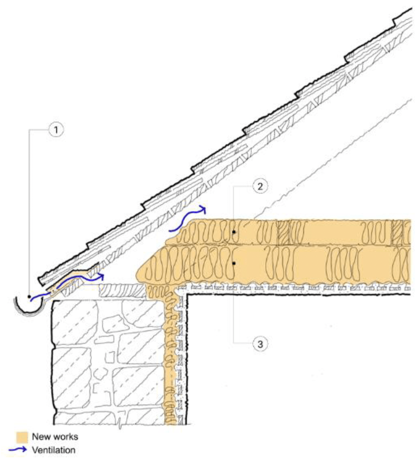
Drawing notes:
1. Eaves ventilation introduced
2. Insulation laid cross ways over joists
3. Insulation laid between existing joists
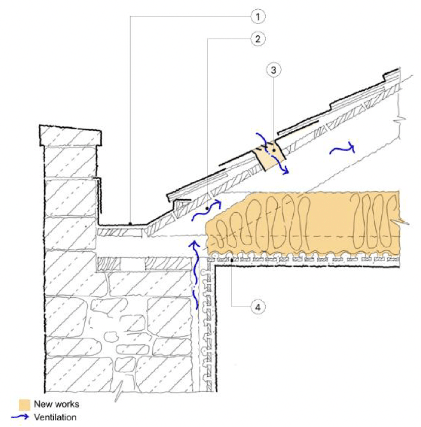
Drawing notes:
1. Parapet gutter.
2. Insulation clear of wall head to maintain airpath.
3. Proprietary slate vent at low level on roof.
4. Existing lath and plaster, retained.
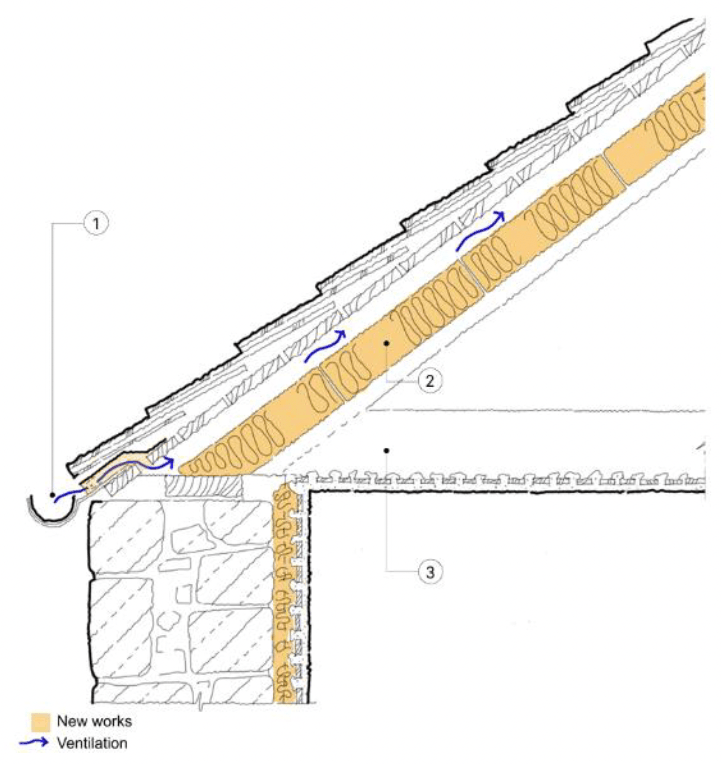
Drawing notes:
1. Eaves ventilation introduced.
2. Insulation batts supported on 20mm timber rails supported on existing rafters.
3. Existing joist.
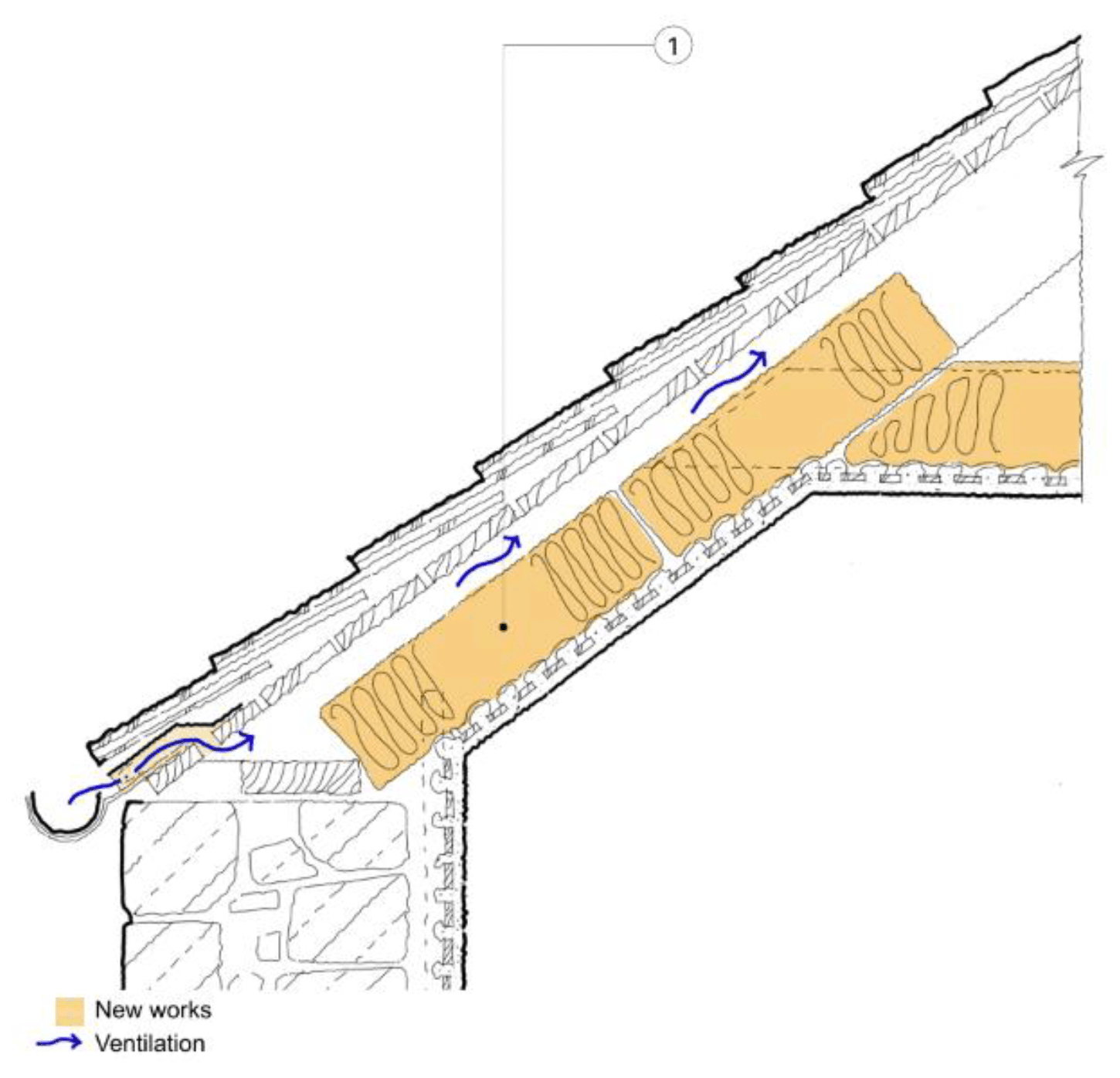
Drawing notes:
1. Hemp batts slid down top of existing lining
b) Control of condensation in pitched roofs
Continuous ventilation, or the equivalent, is essential at eaves level and commonly required at the ridge. Loft insulation should be laid to retain a 50mm gap between the termination of the insulation and the start of the roof at the wall head or wall plate. Under BS 5250, the ventilation gap in a roof void should be enlarged to 100mm in specific scenarios to ensure adequate airflow and prevent condensation. This typically applies to larger roof spans or low pitch roofs which require 100mm air paths.
A traditional uninsulated roof will permit free movement of air between the roof space and behind the lath and plaster. However, adding insulation that seals off the top of the gap at the plaster, while satisfying the requirement of Standard 2.4.1, compromises the free flow of ventilation. Therefore, there is a need to ensure adequate air movement by other means. In this example, the insulation is kept back from the wall head to allow free movement of air between the void behind the lath and plaster and the roof space.
Attention should be paid to features such as loft access and light wells. These should be insulated and draught-proofed to control warm moist air rising into the cold roof space.
Due to the temperature differential between the wall and ceiling plaster (especially at the wallhead), there is an increased risk of both surface and interstitial condensation on the wall at its junction with the ceiling. Careful control of relative humidity and vapour pressure within room spaces is therefore a vital factor in the control of condensation, as is the use of vapour permeable materials compatible with the existing construction.
Condensation is managed in warm roof construction with the retention of a minimum 50mm air gap between insulation and sarking boards, or 100mm in specific circumstances. Rafters are typically deep enough to accommodate this air gap and the insulation depth but where there in insufficient depth this can be achieved through the use of timber battens.
Room-in-roof or coomed ceilings are common in Scottish buildings and require careful attention to avoid introduction of cold bridging and blocking ventilation pathways that increase the condensation risk. A min. 50mm air gap should be left between the insulation board and sarking.
The air tightness of ceilings and walls with lath and plaster on battens, determines how much heat, air and water vapour are transferred by convection. Air tightness can be achieved with good quality plaster, and where historic finishes are retained, these can be patched and maintained to improve this.
The introduction of roof vents, such as slate vents, maybe required following the installation of loft insulation, particularly where bituminous roofing felt is present. Eaves or ridge vents can be used to achieve additional ventilation with minimal visual impact. There is a wide range of roof vents available ensuring the introduction of additional ventilation can be sympathetic to the historic character of the roof.
All pipework and tanks should be on the warm side of the insulation wherever possible.
In the context of BS 5250, longer roof spans and flat roofs require careful consideration in ventilation strategies to mitigate the risk of interstitial condensation. Additional ventilation provisions should specifically be incorporated for flat roofs and spans exceeding 10 metres, including the enlargement of ventilation gaps to ensure sufficient airflow. Mid-span ventilation is also recommended to maintain consistent air movement throughout the roof void, reducing the likelihood of moisture buildup and condensation-related issues. These measures align with BS 5250's guidelines for effective moisture control in building design.
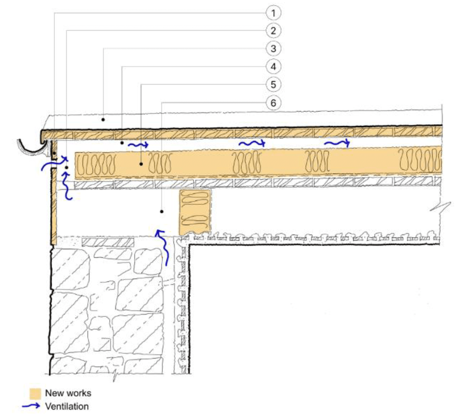
Drawing notes:
1. New fascia with insulation behind to prevent cold bridges.
2. Continuous ventilation slot in fascia.
3. New lead roof on underlay supported on softwood boards.
4. Minimum 50mm ventilated space.
5. Rigid insulation board and vapour control layer on existing timber deck.
6. Existing roof & structure.
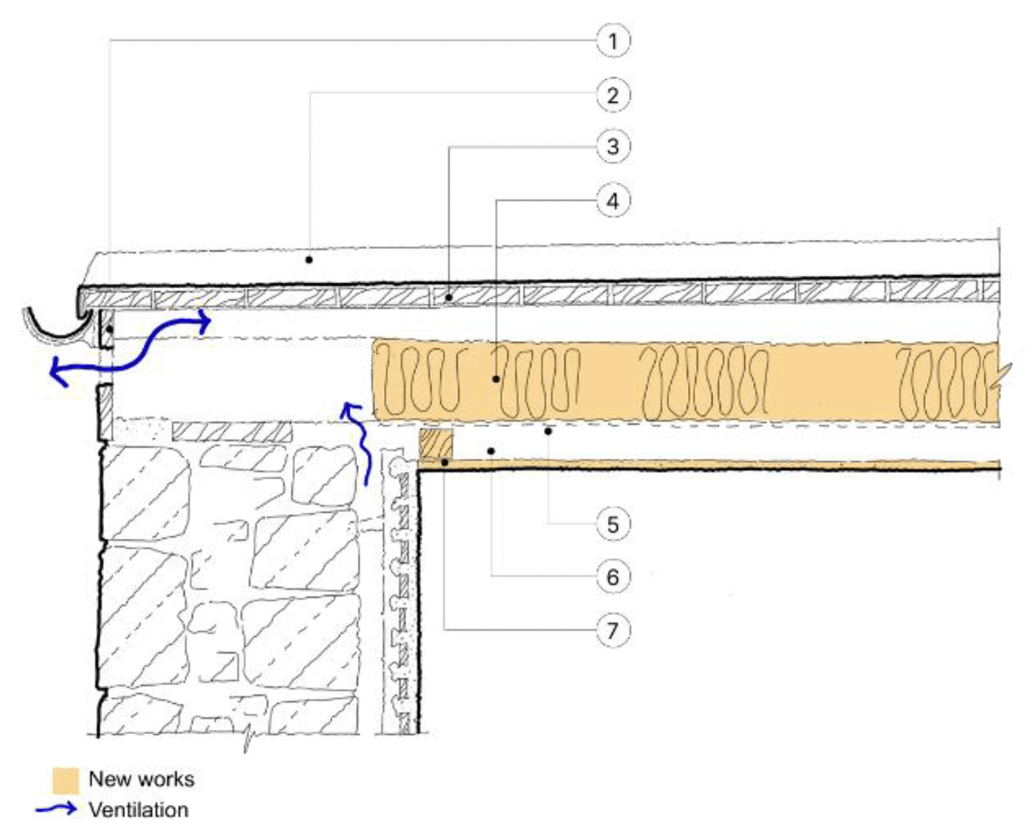
Drawing notes:
1. Existing ventilated fascia to each roof space.
2. Existing lead roof free from lead corrosion.
3. Unrestricted air space.
4. Rigid insulation board above lath and plaster.
5. Vapour control layer.
6. Service void.
7. New plasterboard ceiling on battens.
c) Control of condensation in flat roofs
For existing and new lead roofs, underside lead corrosion (ULC) can reduce significantly the life of lead sheeting. Ventilation of the roof below the lead supporting deck is essential to control this phenomenon. Where the existing ceiling must be retained, illustration 59 offers an appropriate solution, however, it requires the level of the lead roof covering to be raised.
Illustration 60 shows a cold roof solution where the existing ceiling is removed to allow installation of insulation and a vapour control layer. This solution is also appropriate for control of ULC. In accordance with BS 5250 new, cold, level-deck roofs should be avoided due to high risk of interstitial condensation which can be severe and cause failure of structure and insulation.
Where there will be little or no impact on a building of cultural significance, the standard can be met by the introduction of new warm roofs over existing cold roofs. Removal of void ventilation would be required in this circumstance.
When introducing a new warm roof, a continuous and even layer of insulation of sufficient thickness is required to avoid the risk of surface condensation within the occupied space. Achieving continuity of insulation at penetrations and perimeter requires particular attention as failure to address this will lead to cold areas and surface condensation.
For flat roofs, where the covering remains in place and insulation can be installed from below, a 50mm air gap must be maintained on the cold side of the insulation, between the insulation and the support deck for the roof covering. A greater air gap is required where roof spans are longer as per BS 5250. It is essential to introduce a ventilation gap below the support deck when the roof covering is lead or zinc to control condensation and corrosion and reduce potential risk of decay in the decking and structure.
Where the form of the roof must remain unchanged, the introduction of a ventilation path may limit the depth of insulation that can be installed. In these circumstances, a balance should be sought between energy efficiency and retention of historic character and fabric.
Lead valley or parapet gutters should be approached as small flat roofs to ensure that insulation is effective and condensation risk is managed. The underside of lead gutters should be ventilated to prevent corrosion accordingly, but caution should be exercised when introducing new ventilation into existing historic roofs. Attention should be paid to this at the design stage.
d) Condensation on or within floors
Section 10 of BS 5250: 2021 provides guidance on the control of condensation in the principal forms of floor construction. Solid floors can have low surface temperature and absorb heat, while suspended timber floors can introduce cold air. Both can significantly affect thermal comfort and introduce a surface condensation risk. The thermal performance of both suspended timber and solid floors can be improved but this can be intrusive and cause harm or loss to historic fabric. The level of intervention required should be carefully assessed as the introduction of insulation and draught-proofing measures can also increase condensation risk when poorly detailed or incompatible materials are specified.
e) Condensation on or within suspended floors
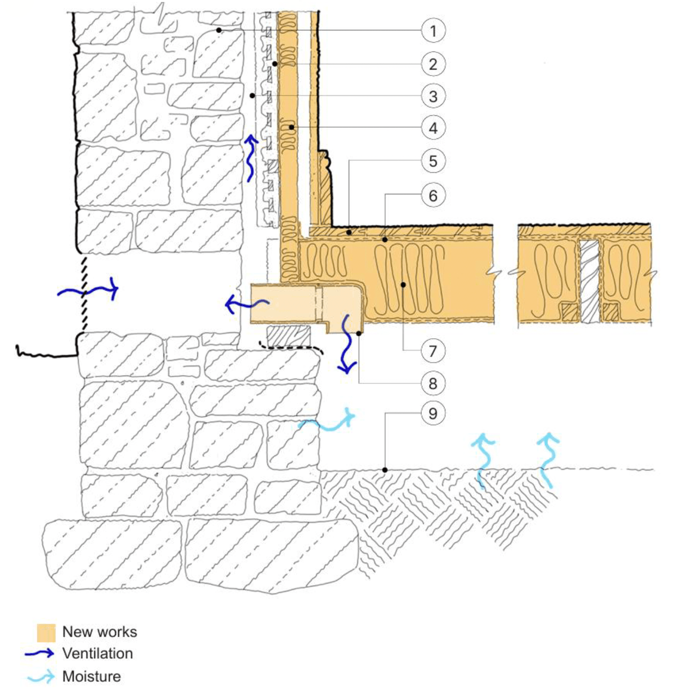
Drawing notes:
1. Masonry wall.
2. Lath and plaster.
3. Vented cavity.
4. Insulation boards fixed to existing plaster with service void and plasterboard finish internally.
5. Existing timber floor removed.
6. Vapour control layer installed across joists under new floor finish.
7. Insulation supported on breather membrane dressed over and secured to joists.
8. Periscope vent required to ensure ventilation of solum.
9. Solum.
Notes on condensation on or within suspended floors (refer also to notes associated with Standard 3.4).
Joists embedded in solid walls can be vulnerable to moisture arriving through capillary rise, water penetration and condensation. In solid-walled buildings, floor joists might penetrate the walls without risk of decay if the above moisture risks are addressed. Timber can also be in direct contact with masonry if it is dry.
BS 5250: 2021 highlights that retrofit of wall insulation and the incorrect use AVCL layers can increase condensation risk. Embedded joists, common in traditional buildings, are difficult to access to provide protection. In addition, this detail is an intrusive, non-reversible intervention that is likely to impact on a building’s significance.
Solum ventilation must be maintained and, where possible or required, enhanced. Continuity with the cavity behind the lath and plaster should be achieved by ensuring the floor insulation does not seal off ventilation paths to the void behind the lath and plaster. However, if the gap is removed because of retrofit work, other ventilation solutions may need to be considered.
Where vertical separating construction is inserted through the building, continuity of the solum ventilation will need to be provided, including the provision of fire sleeves.
If the building is sited in a flood zone or vulnerable to surface water flooding, consideration should be given to closing off solum ventilation as well as the building’s drying requirements to increase resilience and reduce prolonged saturation that would lead to greater condensation risk.
f) Moisture and condensation in solid floors
The existing thermal performance of historic solid floors is often reasonably good when compared to the U-values of walls and roofs. There are two principal causes of damp in solid floors which are condensation and moisture rising from the sub-soil. Rising moisture is drawn up into the floor by capillary forces or the presence of hygroscopic (water attracting) materials such as salts. High moisture content in a floor can be managed if the moisture ingress and evaporation are in balance and unlikely to cause fabric decay. Where a solid ground floor is in equilibrium with its environment, the moisture distribution will be uniform and this can be aided with improvements to ventilation and thermal performance of the building as a whole.
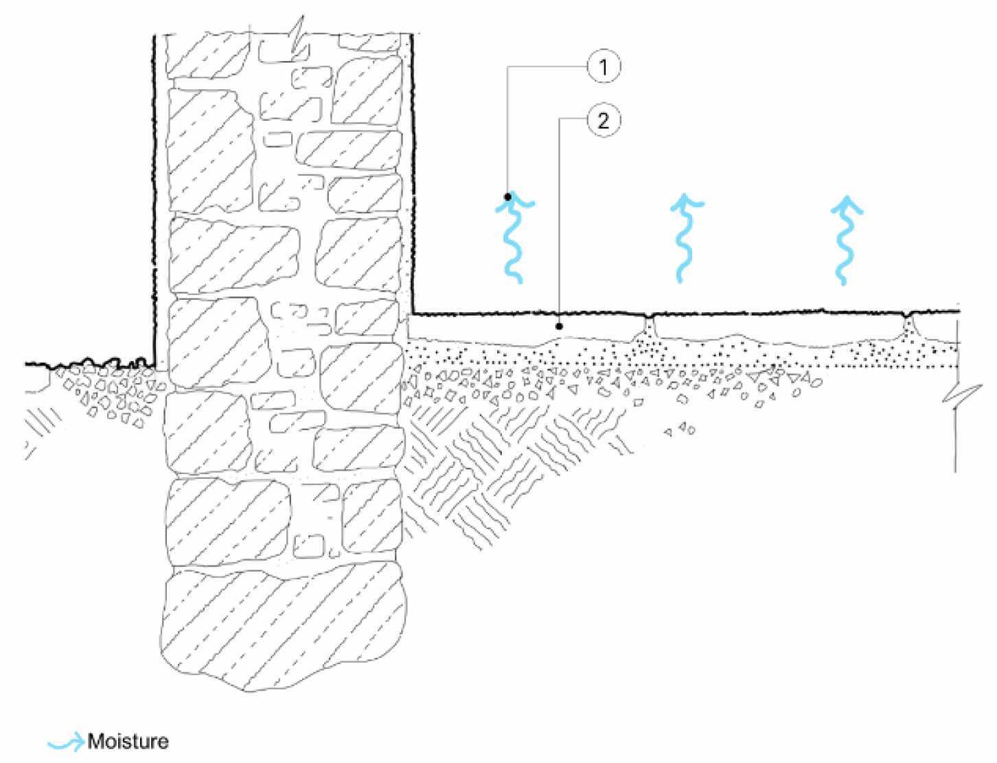
Drawing notes:
1. Moist air removed by evaporation.
2. Existing permeable solid floor.
When a solid floor is in balance with its environment its moisture content is maintained at a level that it will not cause harm. This is because there is a balance between the rates at which moisture is absorbed and released. Permeable materials absorb and release moisture freely.
Notes on moisture and condensation within solid floors (refer also to notes associated with Standard 3.4 Moisture from the ground)
Where a historic floor must be retained in situ a practitioner may have to resolve issues with a surface that is prone to condensation. This might be due to changes in climatic conditions, rapid cycling of higher summer temperatures, higher humidity, or because the rest of the building envelope has been improved. Timber should be isolated from the floor surface to reduce contact with surface moisture. Efficient room ventilation is essential to control relative humidity and vapour pressure.
In many cases, the U-values of existing un-insulated floors can be relatively good when compared with those of walls and roofs. Where an existing floor is retained, specifying lime mortar for any repair or pointing will improve the performance and the floor’s ability to manage moisture.
The addition of insulation should be considered against the level of cultural significance of the building and its historic fabric and by applying the whole building approach. Where existing lath and plaster has been removed or is in poor condition, for example, incorporating thermal improvements through insulation or insulated plaster is likely to be beneficial.
The generally high level of moisture present in traditional solid ground floors normally requires evaporation from the entire floor surface in order to maintain the necessary equilibrium. Any impervious material laid on a solid floor, such as rubber–backed mats or carpets will impede the movement of moisture. This can cause localised concentration and restrict evaporation resulting in accelerated decay of the floor surface.
Insulation which has hygroscopic properties is used under solid floors as this offers a beneficial ‘buffering’ effect during fluctuations in temperature and vapour pressure, thus reducing the risk of surface and interstitial condensation occurring. However, high levels of humidity can still pose problems even when the insulation is hygroscopic.
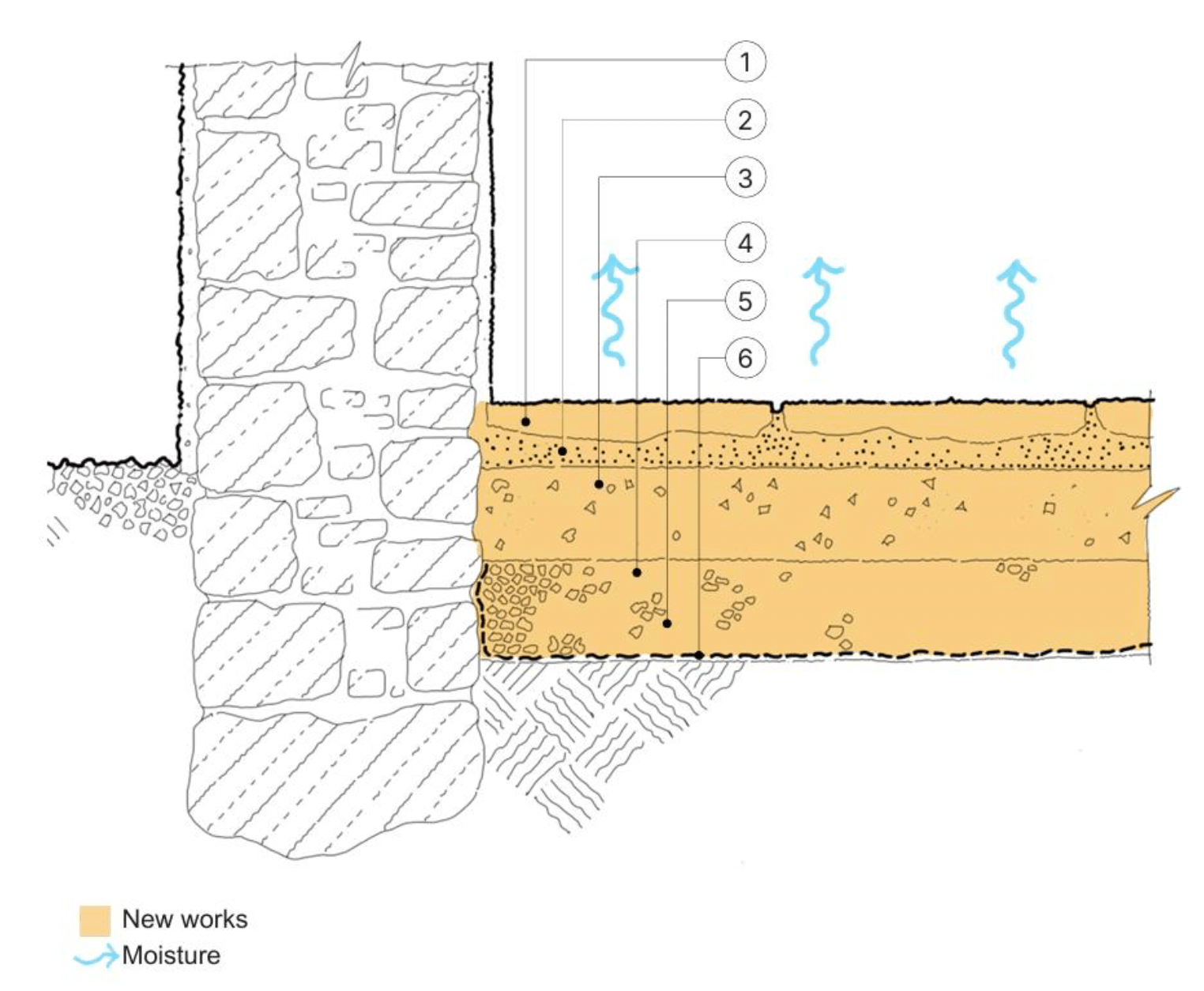
Drawing notes:
1. Permeable floor finish
2. Hydraulic lime screed with fine aggregate
3. Hydraulic limecrete floor slab with insulating aggregate such as expanded clay
4. Insulating layer of lightweight expanded clay aggregate
5. Uptake of ground water prevented by lack of capillaries in expanded clay loose fill layer
6. Breathable geotextile or hessian separation layer laid on levelled and compacted ground
Note: Care needs to be taken not to undermine existing footings when excavating.
g) Condensation within walls
Practitioners should be aware that moisture assessment models used for assessing existing walls might contain inaccurate or missing data in regard to the materials and construction build-up of traditional solid walls.
Assessing the risk of wind driven rain to the existing structure should be done in accordance with BS 8104.
Moisture within a solid wall reduces its thermal resistance and increases the risks associated with excess moisture. To achieve the level of thermal performance required of a heated building, solid masonry can be insulated by applying thermal insulation either externally or internally. Alternatively, if applying insulation is not possible or desirable (because, for example, of the historic or aesthetic value of the existing masonry), then the thermal performance can be enhanced by coherent and regular repair and maintenance. Conversion work should include an assessment of the moisture risk and confirm that adding insulation does not increase moisture risk by either trapping moisture, increasing condensation risk or by lack of vapour transfer.
Maintenance of the void behind the lath and plaster will allow for improved evaporation of interstitial condensation on the inner face of the outer stone wall. Given the restrictions created by Standard 2.4 as mentioned in 3.15.4(a) ii above, it may be necessary to provide alternative means of ventilation to this space.
Providing air circulation within the void behind the wall finish can control the moisture content of adjacent timbers and plaster. However, this is not easily achieved where there are separating floors between dwellings. Illustration 64 shows a possible means of achieving air movement by the insertion of inconspicuous, small-area vents at skirting and ceiling level. Because of the danger of drawing moisture laden air into the cooler void behind the plaster, the vents should not be installed in moisture producing spaces, such as kitchens and bathrooms.
Materials that restrict vapour transfer might have been used in the past for the repair and renovation of a building’s walls. These include highly cementitious renders and plasters, impervious paints and waterproofing treatments, as well as many extensions and ground surface treatments (such as tarmac pavements against external walls). These compromise and complicate both repair and retrofit strategies.
A building that is in heated intermittently is significantly more likely to be the subject of condensation risk. When insulating solid walls, occupancy and heating patterns should be used to evaluate minimum heating levels and manage any condensation risk. Potential inaccuracy in models calculating moisture risk for traditionally constructed walls should be taken into consideration.
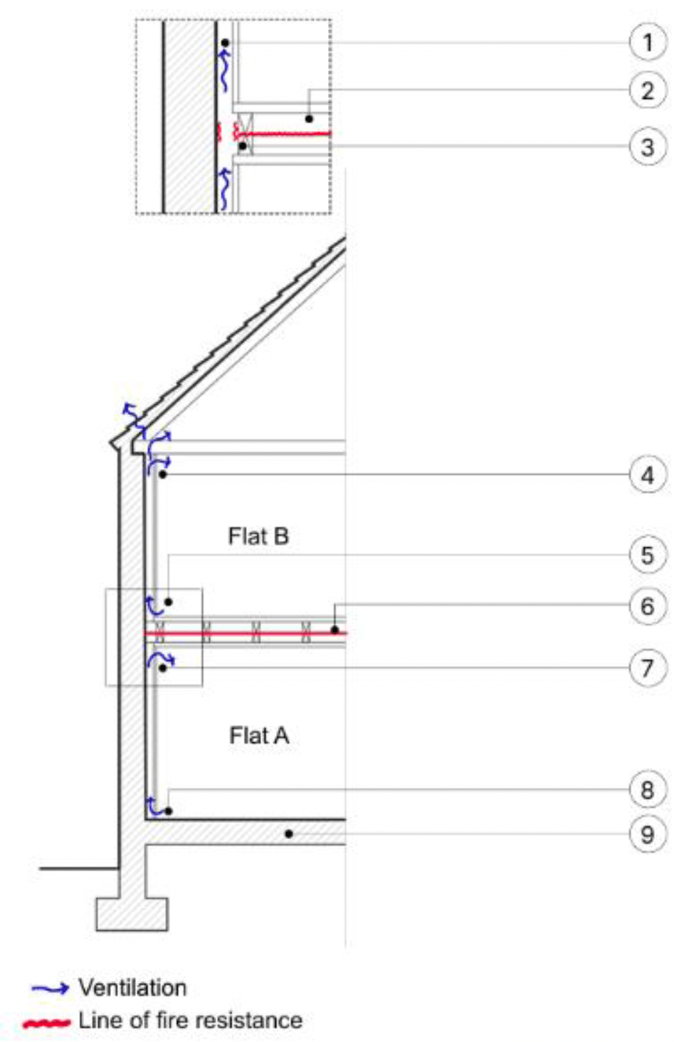
Drawing notes:
1. Ventilation maintained behind lath and plaster
2. Separating floor
3. Vent gap left at perimeter of separating floor with intumescent strips to provide a seal in the event of fire
4. Void behind lath & plaster vented to room
5. Skirting level vent to room
6. Separating floor/wall perimeter sound and fire stopped
7. Void behind lath & plaster vented to room
8. Skirting level vent to room
9. Solid Floor
h) Condensation on single glazed windows
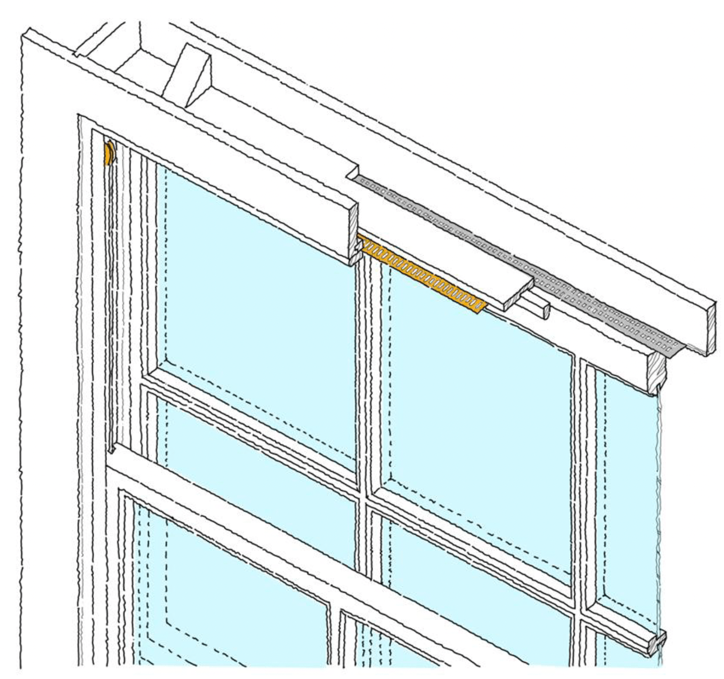
Ventilation may need to be reassessed following draught-proofing of windows to avoid increased internal humidity and a potential build-up of condensation on cooler areas such as glass. In cases where draught-proofing is part of a wider refurbishment requiring a building warrant, it may require the installation of trickle or background vents. In these cases, the practitioner should confirm with the planning authority if an application for listed building consent is also required.
Draught-stripping of sash and case windows will reduce ventilation rates and may necessitate the provision of passive or trickle ventilation, which may be difficult to incorporate into a traditional window frame. For indicative details of trickle vents in sash and case windows, see the HES Short Guide ‘Sash and Case Windows’.
Improving the insulation of a building’s envelope and increasing airtightness is likely to elevate the risk of surface condensation on single glazed windows and poorly insulated returns.
Where historic glazing must be retained, secondary glazing may be installed to improve thermal performance and sound insulation. Detailing to internal insulation should be considered to avoid the creation of a thermal bridge.
Where secondary glazing is the preferred solution, draughtproofing should not be added to the existing windows in order to maintain a ventilated space and prevent the buildup of condensation. Secondary windows should be fitted with a high-quality perimeter seal to prevent warm air from the room entering the cavity, giving rise to condensation and reduced control of the room’s ventilation.
Condensation risk can be minimised for secondary glazing installations if the units can remain closed in cold weather and effective ventilation is provided elsewhere and/or the means of ventilation for the building bypasses the space between the existing and secondary glazing.
Installing double or triple glazing into historic sash frames can improve the thermal performance of the window, but surface condensation can still occur where ventilation to the room is not also improved.
3.15.5 Further reading
Additional guidance on condensation includes (but should not be limited to) the following documents:
- Historic Environment Scotland (2020) INFORM: Condensation
- Historic Environment Scotland (2021) Guide to Energy Retrofit of Traditional Buildings
- May, N & Sanders, C Moisture in buildings: an integrated approach to risk assessment and guidance (White Paper Moisture In Buildings) BSI
- UK Centre for Moisture in Buildings resources
- Efthymiopoulos, S & Aktas, Y. D. (2024) TG 26 Mould in Buildings BSRIA
Contact
Email: buildingstandards@gov.scot