
Conversion of traditional buildings: guidance
This guidance provides a technical insight into the conversion of Scotland’s traditional buildings, balancing building regulation compliance with conservation. It promotes a holistic, risk-based approach to technical compliance in the performance of traditional buildings.
Part of

3.14 Ventilation
Mandatory Standard
Standard 3.14
Every building must be designed and constructed in such a way that ventilation is provided so that the air quality inside the building is not a threat to the building or the health of the occupants.
3.14.1 Application of standard to conversions
In the case of conversions, as specified in regulation 4, the building as converted shall meet the requirement of this standard (regulation 12, schedule 6).
3.14.2 Commentary
The drive to improve the thermal performance of building envelope, through enhanced insulation and reduced air leakage, must be carefully balanced against the risk of creating an unhealthy indoor environment.
Significantly reduced ventilation rates in retrofitted buildings are considered a contributing factor to the rise in respiratory health issues, including asthma. These problems may be exacerbated by mould growth, as well as chemical emissions from contemporary building materials and furnishings. In addition, reduced air exchange can increase exposure to airborne bacteria and other contaminants.
In contrast, traditionally constructed buildings that are well ventilated can offer a comfortable and healthy indoor environment. When such buildings are upgraded sensitively to improve energy efficiency, they can successfully balance thermal performance with good indoor air quality.
Lack of ventilation in traditional buildings is not normally a problem. The nature of these buildings means that there are many sources of incidental natural ventilation, for example through gaps around loose-fitting doors and windows, through skirting and floor junctions, and through roofs and open flues. Such high rates of ventilation have historically meant that these buildings were healthy for occupants (even if they were uncomfortable at times due to cold draughts) and that condensation and mould growth were controlled. In the conversion of these buildings, there is a danger that by trying to improve energy efficiency, air infiltration rates will be reduced to below acceptable standards. This often necessitates additional ventilation to satisfy fresh air allowances required.
This standard is principally aimed at the ventilation of bathrooms, kitchens and other moisture-producing areas. When upgrading the thermal performance of traditional buildings, considerable care must be exercised when selecting a ventilation rate. A minimum ventilation rate that is acceptable for human health and the extraction of moisture may be insufficient to provide ventilation to hidden spaces, which could lead to raised moisture content in vulnerable materials such as plaster and timber.
Ventilation is therefore necessary to maintain a healthy building fabric as well as healthy conditions for occupants. The introduction of vapour control layers (VCLs) and other membranes when insulation is added will further reduce the air permeability of the construction. However, for traditional Scottish masonry construction, the amount of air movement required to maintain a moisture balance and to prevent the development of dry rot in timber is relatively low. To prevent the occurrence of condensation and mould growth on surfaces it is important to ensure that humidity levels are kept below 70- 75% RH by a combination of both adequate ventilation and space heating.
CO2 levels over 1,000 ppm can indicate poor ventilation rates, and may also be associated with the presence of higher levels of other contaminants, such as volatile organic compounds, formaldehyde, particulates, bacteria, etc. The levels of these other contaminants are less easy to identify accurately without very sensitive testing equipment.
3.14.3 Issues to be considered
Typical risks in the conversion of historic/traditional buildings
1. Control of humidity
The internal surface temperature of poorly insulated building envelopes naturally fluctuates with the external air temperature to a greater degree than that of well-insulated constructions. The risk of condensation is much higher where warm vapour laden internal air interacts with colder surfaces associated with a lack of insulation. These may be spaces where insulation measures have been poorly designed or spaces which are uninsulated such as loft spaces above insulation. Appropriate ventilation must be maintained to keep the internal air in contact with external wall surfaces below 70% RH (above 70% RH moulds may develop). This can be done through a carefully designed natural or mechanical ventilation strategy.
Implementation of mechanical ventilation systems and their associated ductwork, flues, fans, etc. may negatively impact the historic character and cultural significance of a traditional building. This could occur from external plant placement or from internal runs of ductwork interrupting historic spaces. Care should be taken to ensure mechanical ventilation systems are designed to minimise the impact to high-value spaces within a building.
2. Natural ventilation
Sealing up openings (draught-stripping) and open flues to conserve energy reduces airflow within rooms and hidden spaces and may upset the moisture balance in materials and promote decay.
3. Background ventilators
The unsympathetic introduction of background ventilators into traditional sash and case windows (and other traditional windows) may adversely affect the historic character of the windows and wider building. Whilst this may decrease the risk of condensation on the windows themselves, window mounted background vents can be isolated by curtains or blinds leaving the rest of the room underserved.
Window vents can be installed to provide background ventilation. Where this is inappropriate in buildings of higher cultural value, background ventilators may be placed elsewhere in a room. This will have less impact on the fabric and appearance of the windows, but the likely impacts on external facades and internal character from additional service penetrations should be fully considered.
4. Passive stack ventilation systems, mechanical ventilation and mechanical aids to ventilation
Passive Stack Ventilation (PSV) and ducted forms of mechanical ventilation can be very disruptive to a building’s historic fabric and character where ducts intrude into spaces and pass through walls, floors and roofs.
Location of vents in the external fabric (walls and roofs) may affect historic character and their installation can be destructive to fabric, particularly in earth and rubble-type walls. Routing and positioning of fans and associated ductwork can be challenging and destructive to building fabric if not carefully designed.
Location of plant can be visually intrusive, and a large system may overload structural elements. An understanding of the plant and the structural capacity of the building is crucial.
Location and design of PSV controls may be intrusive to sensitive spaces. A PSV system in a building can be ineffective where wind suction is insufficient to prevent moisture build-up in spaces.
5. Air movement in voids
Ventilation may be affected adversely by energy conservation measures that reduce air infiltration into voids. Ventilation systems designed and installed to meet the requirements of building occupants would not usually consider this issue.
6. Installation of CO2 monitor in principal bedroom
Standard provides guidance on required location of the monitor for effectiveness. There may be space constraints and aesthetic considerations within a traditional building that make correct siting of the monitor difficult. Care should be taken to ensure that location of the monitor is not disruptive to the character of the room and its features.
3.14.4 Recommendations to meet the standard
Wherever possible, the natural ventilation system of a building’s traditional construction should be preserved. Materials and construction introduced to improve thermal performance should be carefully positioned (and held in place) to avoid blocking existing ventilation routes and systems. For example:
- Insulation blocking eaves vents.
- Insulation blocking the open spaces behind framed-out walls and roof spaces, or between these open spaces on different floors at floor and wall junctions.
- Insulation blocking the connection between floor voids and wall voids.
- Membranes or insulation blocking wall vents to floor voids.
There are two common physical problems in relation to the normal provisions for ventilation that are encountered in the conversion of traditionally constructed buildings:
a) The first is that it can be difficult to incorporate background ventilators in existing windows (or to provide them elsewhere). For buildings of greater cultural significance, it may be inappropriate to alter the window joinery. In these cases, the insertion of ventilators in plain plasterwork and through external walls may be preferable if it can be achieved in a way which doesn’t impact on the wider character of the building.
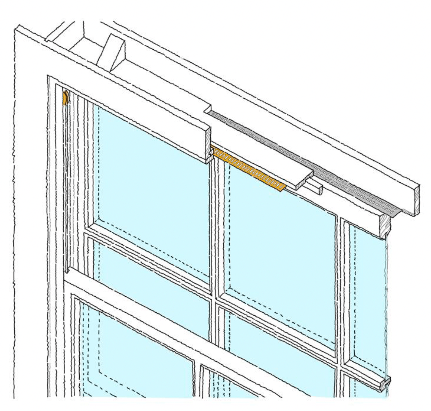
Where some alteration to the window joinery is regarded as being appropriate, background vents can be created by cutting holes into the head of the casement above the lower sash and above the upper sash as indicated in illustration 50. Alternatively, if background ventilation is required at the top of the window, the system shown in the illustration can be adopted. Fitting proprietary background vents in the frame and meeting rails of the sash itself is not recommended as this is likely to weaken the joinery sections and the ventilator can look obtrusive. Further information on the installation of background ventilators can be found in Historic Environment Scotland’s Technical Paper 6: Indoor Air Quality and Energy Efficiency in Traditional Buildings and INFORM guide Ventilation in Traditional Houses.
b) The second issue is that it is not always possible for windows alone to provide the required amount of natural ventilation based on their opening area. This is because their position and size are fixed by the historic elevation. The practicality of using openable windows also depends upon the location of the building and the immediate external environment. In noisy or polluted urban areas, for example, it may not be possible simply to open windows for increased ventilation. Security risks are also a concern, and safety measures often retrofitted to existing windows to keep out intruders may not be appropriate to many historic windows. Even if windows can be opened securely without the introduction of noise and pollution, building users often do not open windows in the winter months to allow for appropriate ventilation as it will cause cold draughts.
Several ventilation options are available for dwellings, each with its advantages and disadvantages. Reference should be made also to the Energy Saving Trust’s Good Practice Guide 268 section 5 for more detailed information. The systems most commonly applicable are:
- Decentralised Mechanical Extract Ventilation (DMEV)
- Passive Stack Ventilation (PSV)
- intermittent local extract fans (extract only) and background ventilators
- single room heat recovery ventilation (SRHRV)
- continuous mechanical extract ventilation (MEV)
- continuous whole house mechanical ventilation with heat recovery (MVHR)
a) Passive and mixed mode systems.
If openable windows alone are insufficient or inappropriate for ventilation in larger-scale commercial buildings, then other forms of natural ventilation can be considered. Generally, these will rely on creating other ventilation openings in the building, and ducting air from these openings into the spaces. These ventilation openings will often be at roof level to avoid pollution and noise and minimise interference to the building’s character and historic fabric.
These installations may work on a purely ‘passive’ basis, relying upon the natural forces created by wind movements and temperature differences to draw fresh air into the building and then up an exhaust stack to discharge at roof level. This type of installation is referred to as a passive stack ventilation system (PSV), which can also be used in domestic-scale buildings. If there are periods during which these natural forces are not adequate to generate the necessary air movement, fans can be installed at the head of the exhaust stack to draw the air through the system. This is what is termed as a mixed mode system.
Mixed mode systems utilise comparatively low fan power, and then only when fan assistance is required, and so can assist in achieving the requirements under Standard 6.6, which relate to the efficiency of mechanical ventilation systems. The standard requires that domestic properties have adequate means of purge ventilation. This may be achieved through openable windows or mechanical extract systems with a suitably high extract rate and should comply with the air change rates set out in the Standard.
Passive or mixed mode ventilation systems require complex calculations and usually dynamic thermal modelling to ensure that they will work correctly so suitably qualified engineers would be required to prepare the designs. Additionally, ductwork and openings at roof level may need to be quite large to have the desired effect. Therefore, complex traditional or historic buildings will normally require specialist engineering input even when simple ventilation systems are to be used.
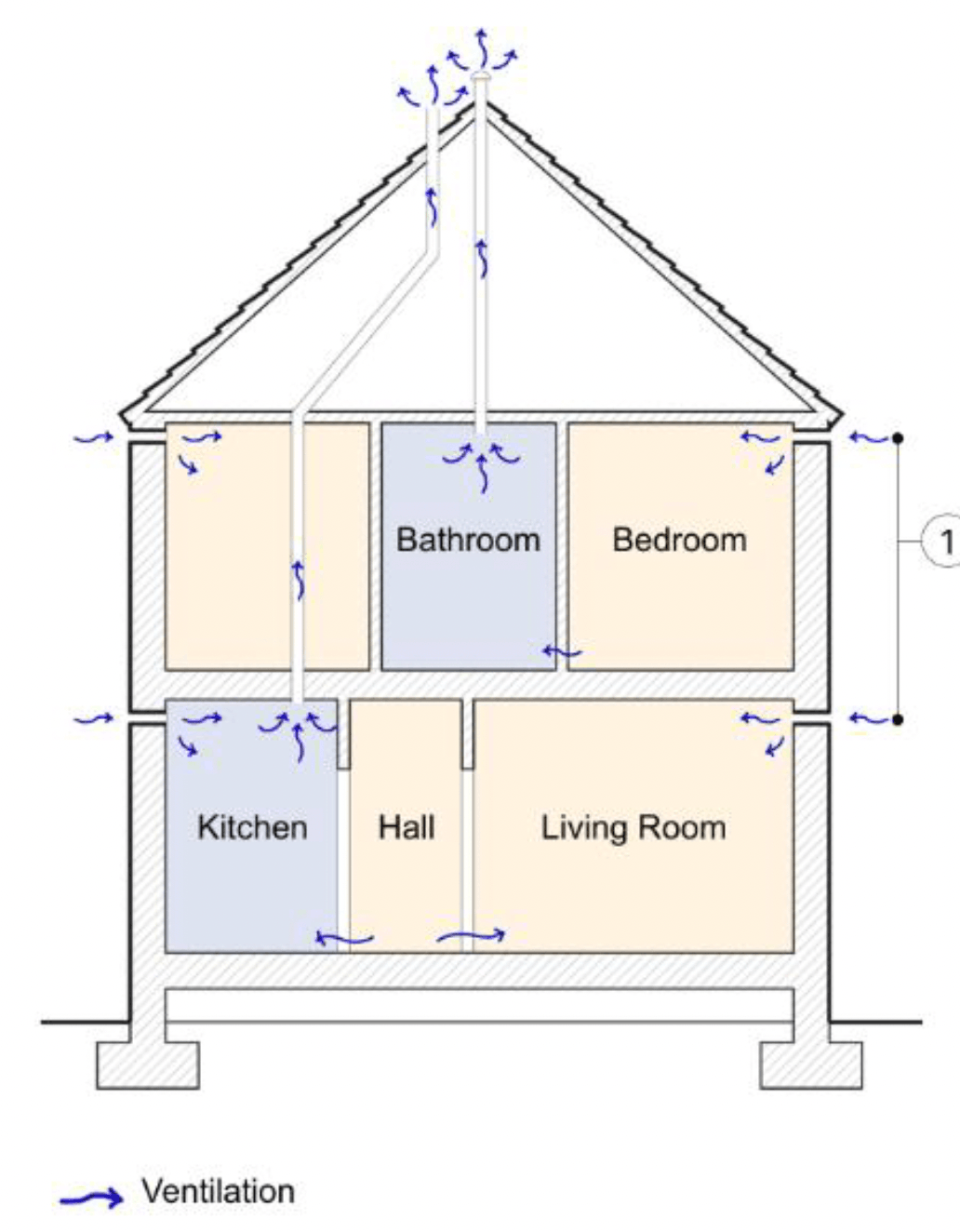
Drawing notes:
1. Vents in walls or windows
b) Local extract fans
Local extract fans are positioned in high moisture producing spaces to extract moisture and other pollutants. They are not normally operated continuously and may be operated by the occupant or by a humidity-sensor control (sited close to the main source of moisture generation) with replacement air provided by background ventilation. The extracted air is ducted to the outside and the positioning of the extracts needs to be carefully controlled to avoid damage to historic character and to prevent drawing combustion gases into a room from open-flued appliances. Consideration should also be given to the location of the exhaust air terminals and their exposure to prevailing winds which may impact on extract rates. This may involve changing the location of extract terminals or using constant volume flow rate units. Positions of SVP outlets must also be considered when siting extract outlets.
c) Continuous mechanical ventilation system
In dwellings or domestic-scale properties, a practical and energy efficient solution is to install a continuous mechanical ventilation system complying with the provisions of BRE Digest 398. There are two main forms of such systems:
i. extract only, and
ii. balanced supply and extract.
Both can be designed to comply with the building standards using proprietary equipment for small-scale applications.
The extract only system relies upon leakage into the building for make-up air. In traditional buildings with sash and case windows and/or sub floor vents, the infiltration through these will generally be adequate for such a system to function properly. Where airtightness has been improved, including draught-proofing of windows, doors and floors, is important to ensure that sufficient air infiltration will be available from other sources.
The balanced supply and extract system delivers air as well as extracting it and does not rely on any infiltration. The balanced supply and extract type of system can also be provided with a crossflow heat exchanger to recover some of the heat from the exhaust air and pre-heat the incoming fresh air. These systems contribute to the energy efficiency of the building and can help with the energy performance requirements under 6.6, but additional space is required for the plant involved.
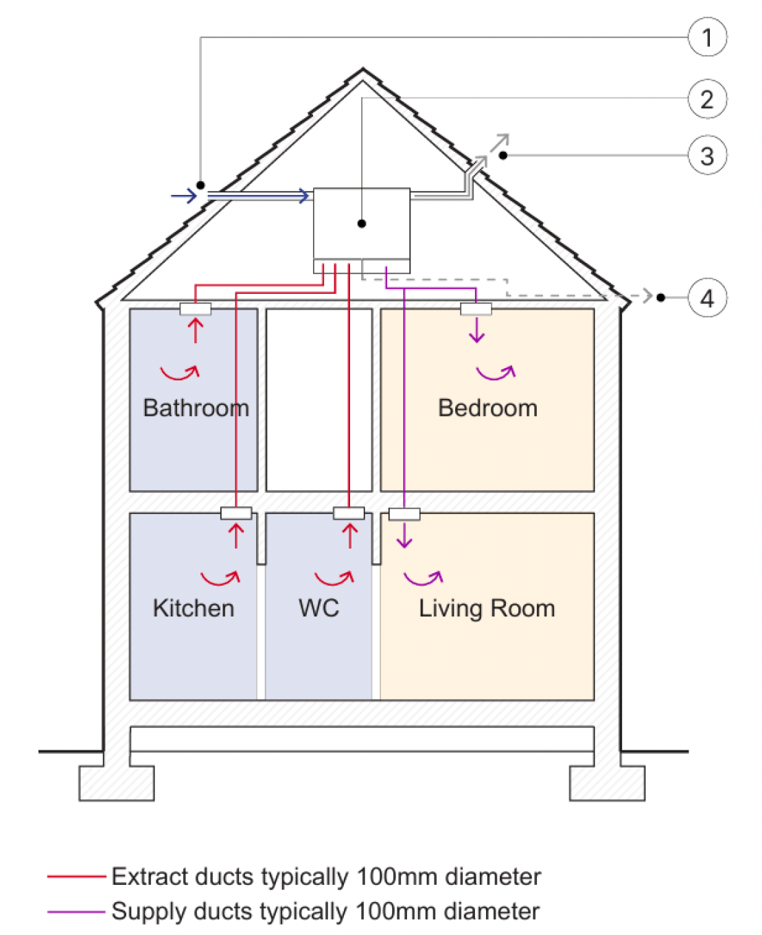
Drawing notes:
1. Fresh air intake from outside
2. Cross-flow heat exchanger to recover heat from extract air
3. Exhaust to outside
4. Condensate drain
Both systems require a location for one or more (in larger properties) central fan units, which will be ducted to outside: one duct for the extract only system and two for the balanced supply and extract system. The size of these ducts depends upon several factors, which require calculation, but typically they would be around 150mm to 200mm diameter in proprietary systems of a domestic scale. The routing of ducts must be carefully designed to minimise damage to a building’s character and its historic fabric and will require appropriate fire stopping and sound insulation (for dwellings) at penetrations in separating floors and walls.
Thermal insulation on ductwork should also be carefully considered to avoid condensation forming in or on the ductwork. As a minimum, the intake and exhaust ductwork on a balanced heat recovery system should be highly insulated to avoid condensation, and supply/extract ductwork should be insulated where it passes through cold voids. These systems offer several advantages over discreet extract or supply fans. A typical small building might require three or four individual fans for toilets and kitchens and each of these fans will require a wall or roof penetration.
A central continuous system can achieve the same or better standard of ventilation with one or two penetrations, which can be located in such a way as to minimise interventions with the fabric and provide the best location for the air intake or exhaust in relation to the surrounding environment. These systems are also typically quieter in operation and less visually intrusive.
Many traditional buildings, from which air is being mechanically extracted, will allow sufficient replacement air to infiltrate into the space from an adjacent area around and below existing doors. To comply with the standard for 4000mm2 of background ventilation, additional unobstructed air space can be achieved by such infiltration, if this has been accurately determined and is capable of being inserted into the existing construction. This does not necessarily have to be provided by way of holes in the door. Cutting 5mm off the bottom of a standard 826mm door will provide 4000mm2 of ventilation space for replacement air to pass through.
d) Ventilation outlets through roofs
The introduction of roof vents into historic roofs needs to be carefully considered and designed. How this is achieved depends on the significance of the building and, particularly, of the roof and roofscape. Among the factors to be considered are:
- Outer, visible roof slopes should be avoided for any ventilation outlets.
- Traditional buildings often have hidden valleys and roof slopes where new roof vents will have a minimal visual impact.
- Hidden, simple ‘straight-through’ vent pipes with carefully formed lead collars (rather than short-life, tin rubber collars) should be considered.
- Where a larger free ventilation area is required, small additional pitched dormer-vents can often be incorporated (Illustration 53).
- Inset-dormer vents are usually less obtrusive than projecting dormer vents (Illustration 53).
- Opportunities should be sought to reinstate historic ridge ventilators where these have been removed previously.
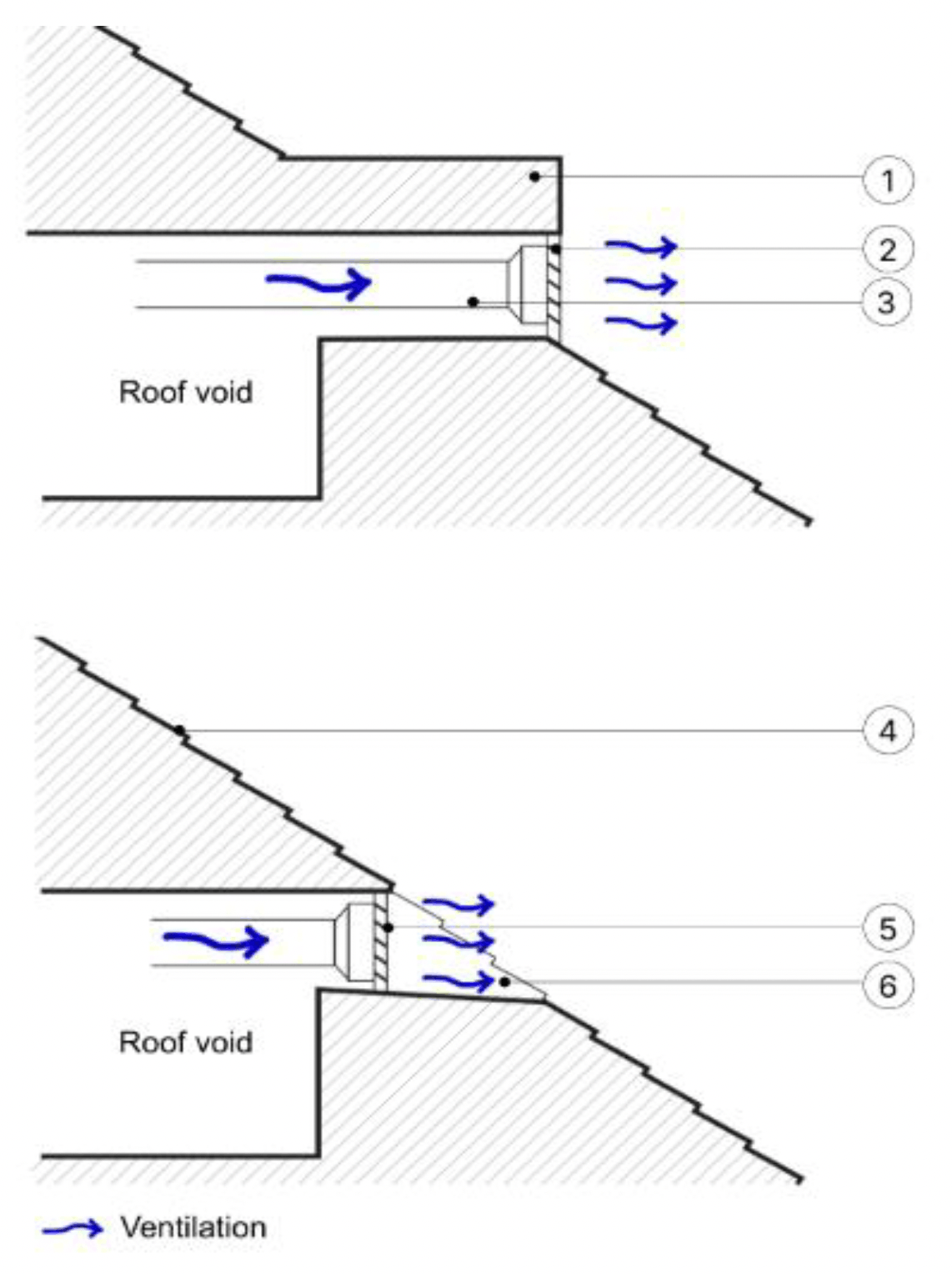
Drawing notes:
Slated roof with projecting dormer extract vent:
1. Slated dormer roof
2. Aluminium louvre vent
3. Vent duct from large kitchen
Slated roof with recessed extract vent:
4. Slated roof
5. Aluminium louvre vent
6. Lead-covered side cheeks and sill board
- Where the vent is to be positioned onto a visible roof slope, a proprietary flush-with-pitch plastic or metal vent can be used (Illustration 54).
- Dormer vents may introduce cold bridging and can be difficult to design and install. Care should be taken to mitigate cold bridging.
- Other types of roof vents may be used depending on circumstances. Examples include ventilated eaves or ridges achieved through raised fireclay vents or raised ridge roll and lead flashing details within continuous lead or zinc roofs. Often in traditional buildings there are redundant chimney flues which may also provide a way of terminating a ventilation system.
- Chimney flues can sometimes be accessed from the roof space and adapted to function as ventilators for it.
3.14.5 Further reading
Additional guidance on ventilation can be found in the following publications by Historic Environment Scotland:
- Historic Scotland (2008) INFORM: Ventilation in traditional houses
- Historic Scotland (2009) Technical Paper 06: Indoor Air Quality and Energy Efficiency in Traditional Buildings
Contact
Email: buildingstandards@gov.scot