
Conversion of traditional buildings: guidance
This guidance provides a technical insight into the conversion of Scotland’s traditional buildings, balancing building regulation compliance with conservation. It promotes a holistic, risk-based approach to technical compliance in the performance of traditional buildings.
Part of

Section 5: Noise - Application of the noise standards: 5.1 Noise separation
Mandatory Standard
Standard 5.1
Every building, which is divided into more than one area of different occupation, must be designed and constructed in such a way to limit the transmission of source noise from normal domestic type activities, between such areas, to a level that will not threaten the health of, or cause inconvenience to the building occupants.
Limitation:
This standard only applies to a building in different occupation incorporating:
a) attached dwellings
b) attached residential buildings, or
c) a roof, walkway or access deck located directly above an area that is either a dwelling or a residential building.
5.1.1 Application of standard to conversions
In the case of conversions, as specified in regulation 4, the building as converted shall meet the requirement of this standard (regulation 12, schedule 6).
5.1.2 Commentary
The issue of sound insulation in the conversion of a building to dwellings such as flats presents significant challenges to the designer. Recommendations and methods used for upgrading the sound insulation in separating walls and separating floors in a building being converted are set out in ‘Housing and Sound insulation – Improving existing attached dwellings and designing for conversions’ (Arcamedia, 2006). The most common type of conversion for traditional buildings is their subdivision into smaller dwellings such as flats or maisonettes, making this standard particularly important.
This guidance is focussed on traditional buildings, and the bulk of these are generally acknowledged to have been built before or around 1919. The majority of these will share similarities in the traditions of construction, essentially being built with mass masonry walls that have lath and plaster internally, and timber floor and roof construction. There is considerable variation in the construction of traditional buildings if, for example, they are a rubble thatched cottage or a large mill building with vaulted brick fireproof construction. However, the bulk of Scotland’s traditional buildings will usually display many of the same traditions in construction and detailing.
Despite this, designers should recognise that most older buildings are unique. Some may not follow standard design or construction but most of them will have undergone some sort of alteration over the generations as outlined in the introduction. Each building will therefore display unique characteristics as far as sound transmission is concerned. These typically arise due to the presence of hidden voids within the construction, back-to-back fireplaces and cupboards, gaps between construction elements in floors and walls and other unpredictable features.
This means that to use standard sound-insulating construction specifications, selected from manufacturers’ product information sheets, may prove to be unsatisfactory when the conversion has been completed. Most importantly, due to the significant influence of sound transmission occurring via walls or floors adjoining the main separating wall or floor, (known as flanking or indirect sound transmission), such sound pathways may be the limiting or dominant factor to achieving sufficient performance levels.
a) Pre-conversion sound test
It is strongly recommended that a pre-conversion sound test is carried out prior to the start of any conversion work, ideally during the site survey process. The sound performance of the existing construction can then be established to inform the design and specification of the conversion scheme. If any problems are identified, this will provide an opportunity to design a tailored acoustic solution and identify any associated costs at an early stage in the project.
The costs of remedial work when a post-completion sound test has failed could be significant in terms of direct labour and material costs and in the loss of time, all of which adds to development costs. Pre-conversion sound insulation testing can also avoid over specification, reduce impacts on existing historic or architectural features and reduce the quantity of materials used thus also potentially reducing the embodied carbon of site works.
b) Layout
Planning the layout of the accommodation will help to reduce noise nuisance. Noise from living rooms or kitchens can be a source of complaint when adjacent to an adjoining dwelling’s bedrooms. If possible, rooms of similar use in adjoining dwellings are best located above, below or directly adjacent to each other.
c) Separating floors
In some cases, unaltered traditional timber separating floors can often achieve the sound performance level without any upgrading work. However, this would need to be established by carrying out a pre-conversion sound test to establish the performance of the existing separating floor. Upgrading an existing separating floor, which may or may not already have some form of sound insulation (such as a timber floor with ash pugging), will be a common requirement in a conversion.
Lightweight timber floors will tend to be the floor type most commonly encountered in the conversion of a traditionally constructed building into individual flats. The treatment of a separating floor to resist airborne and impact sound transmission can be particularly destructive to historic fabric. Therefore, emphasis is placed on how best to deal with this floor type.
Conversions of buildings with concrete and fireproof brick-arched floors are typically encountered in former warehouses, office buildings and hospitals, as they are more popular for converting to flats. The mass of existing concrete floors, if sufficient, may achieve the required airborne sound insulation levels. However, it is unlikely that the existing impact sound transmission levels will be sufficient. This normally requires separating floors to be upgraded such as by specifying resilient layers or impact sound deadening linings.
d) Separating walls
Existing separating walls in traditional buildings are likely to be built from stone or brick and will normally meet sound insulation performance levels, depending on their thickness and overall mass. Solid core stone walls are normally made of stone rubble walls 400 – 800mm thick, lined with lath and plaster on timber studs fixed into the core wall structure, and are likely to perform well in airborne sound insulation tests.
It is generally the case that a solid core stone wall can achieve the airborne sound insulation performance levels in Section 5 of the Technical Handbooks, without further upgrading work providing the walls are:
- in a good condition with no previous service chases,
- have not been substantially altered during the life of the building, and
- are complete structures with no voids or doorways.
Several factors influence the sound insulation of separating (party) walls:
- joists spanning into separating walls (particularly thin spine separating walls),
- flues, fireplaces, recessed cupboards and other recesses in separating walls providing concentrated weak spots for sound transmission,
- damage to lath and plaster finishes, or their replacement with plasterboard, reducing the acoustic performance of the wall,
- penetration of services,
- poor workmanship, such as partially filled mortar joints.
5.1.3 Issues to be considered
Typical risks in the conversion of historic/traditional buildings
a) Flanking Transmission
The major risk to historic buildings from flanking sound transmission arises from the need to provide sound insulation at external wall-separating floor junctions. Fire stopping at such junctions is also a factor. Sealing these junctions reduces or prevents air movement within cavities and behind dry linings and may lead to stagnant air conditions promoting raised moisture levels in adjacent timber. Prevention of conditions conducive to dry rot must be a priority.
b) Separating Floors
Potential loss of historic floor finishes when a floating floor is used to combat impact sound.
- Alterations to historic doors (door heights and proportions) and wall finishes due to raised floor levels,
- Potential loss of ceiling finishes and decorative features when an acoustic ceiling is installed,
- Reduction in floor to ceiling heights may affect historic character,
- Increased floor loading may require structural intervention to strengthen floor,
- Reduced air movement in voids (see above).
c) Separating Walls
The risks are mainly associated with lightweight or slender party walls where the application of sound insulation will result in loss of existing finishes and changes in room dimensions.
- The application of acoustic wall lining to lightweight common access stairs where a large house is converted to flats can result in the loss of decorative cornicing to both sides of the wall.
- Blocking up of doorways that are no longer necessary. False openings, however, can be constructed within the acoustic wall to house the original door and its architraves.
d) Ventilation of Voids
Consideration should be given to the associated risks of ventilating voids to enable the circulation of area which make create an additional risk in relation to the passage of fire or noise. Please refer to Section 2 (Fire), 3 (Environment) and 6 (Energy) of Part 2 of this document.
5.1.4 Recommendations to meet the standard
In many situations where a building is being converted, alterations to separating floors and separating walls to improve sound insulation will almost certainly be required if the standard is to be met. In a small number of cases, the cultural significance of a building or its interiors might be such that the impact of proposals will recommend against a conversion scheme as a viable option for the building.
The unique nature of traditional buildings means that a pre-conversion sound test of existing construction should normally be carried out. This will allow the sound insulation performance of the existing construction to be established and inform a design that will cause least disruption to historic fabric and finishes.
The Technical Handbooks identify two means of meeting the standard:
a) example constructions (providing separating wall and separating floor details), or
b) other constructions, and both should have a sound test carried out under the post-completion testing requirements.
The use of example constructions is not usually directly applicable to traditional buildings as they are generally designed for new buildings. The details illustrated are for guidance only and it is likely that they will have to be amended to suit site conditions.
Upgrading for separating floors
The following details focus only on examples of upgraded separating floors and SVP lining details to meet the building standards.
1. Timber separating floors
Floor Type 1 – A traditional pre-1919 timber separating floor with a suspended lath and plaster ceiling (illustration 80)
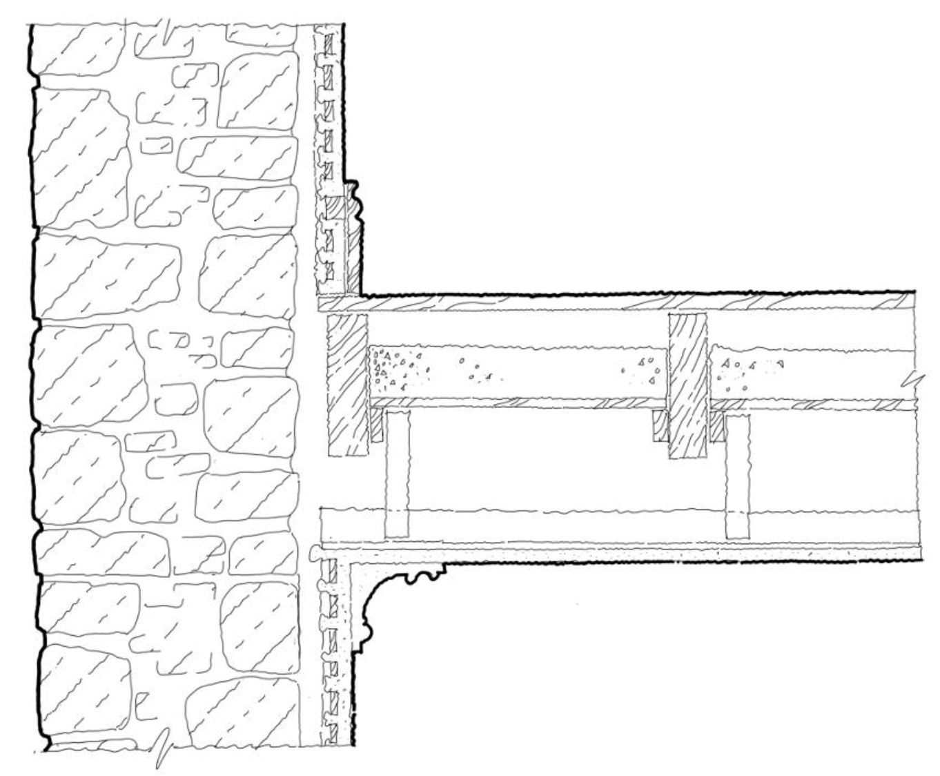
Some pre-1919 ceilings are suspended on timber hangers. This helps isolate airborne and impact sound transmission.
When Undertaking Remedial Work:
- Pay particular attention to the deafening where floor damage may have occurred (e.g. kitchens, bathrooms, along central heating and water service runs and perimeter voids)
- Ensure, where possible, that the lath and plaster ceiling should always be retained
- Ensure patching of lath and plaster ceiling to be a minimum of 2 layers of high-density gypsum based boards (minimum 12.5mm at 10kg/m2)
- Ensure service ducts detailed through the Separating Floor are to be boxed with a timber or metal frame lined with minimum of 2 layers of 15mm high density gypsum-based board (minimum 12.5mm at 10kg/m2). Service pipes should also be wrapped with 25mm quilt insulation (minimum 10kg/m3). Voids in deafening around service runs to be made good in line with the guidance given for the insulation
- Ensure gaps of over 25mm in ceiling or floor to be packed with mineral fibre (minimum 10kg/m3) then sealed with caulk
Note: Refer to Section 2: Fire, for guidance on ceilings and wall linings.
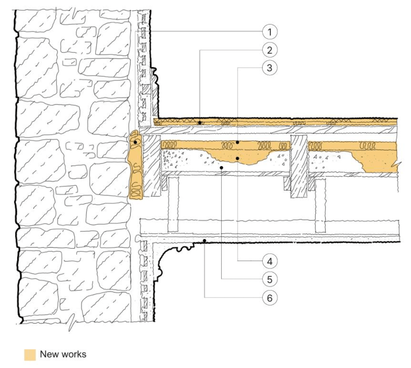
Illustration 80 shows upgrading by retaining the existing suspended lath and plaster ceiling and using insulation within the floor and a shallow floating floor treatment. This minimises the increase in floor level and retains the existing ceiling. This floor system will be marginal in meeting the airborne sound insulation performance, but it does retain the original ceiling features.
Drawing notes:
1. Minimum 33kg/m3 mineral fibre quilt packed into void at wall junction.
2. Acoustic deck treatment is primarily composed of a resilient layer underneath a decking with tongue and grooved edges, such as chipboard or MDF. The treatments vary in thickness from 15mm to 55mm. Shallow platform floor systems of 15mm to 55mm thickness often have the resilient layer pre-bonded to the decking itself. For most systems services and underfloor heating should not be installed within the resilient layer zone as this may cause bridging, reducing the potential impact performance.
3. Minimum 25mm mineral fibre quilt (minimum 10kg/m3).
4. Granular remedial treatment of similar density and depth to existing deafening: traditional ash (75mm), or 2-10mm limestone chips (60mm), or 2-10mm whin aggregate (60mm), or dry sand (50mm) Figures in brackets show approximate thickness required to achieve 80kg/m3.
5. Ash deafening on deafening boards.
6. Lath & plaster ceiling.
Note: Refer to Section 2: Fire, for further guidance on ceilings and wall linings and Section 3: Environment, for ventilation of wall cavity voids.
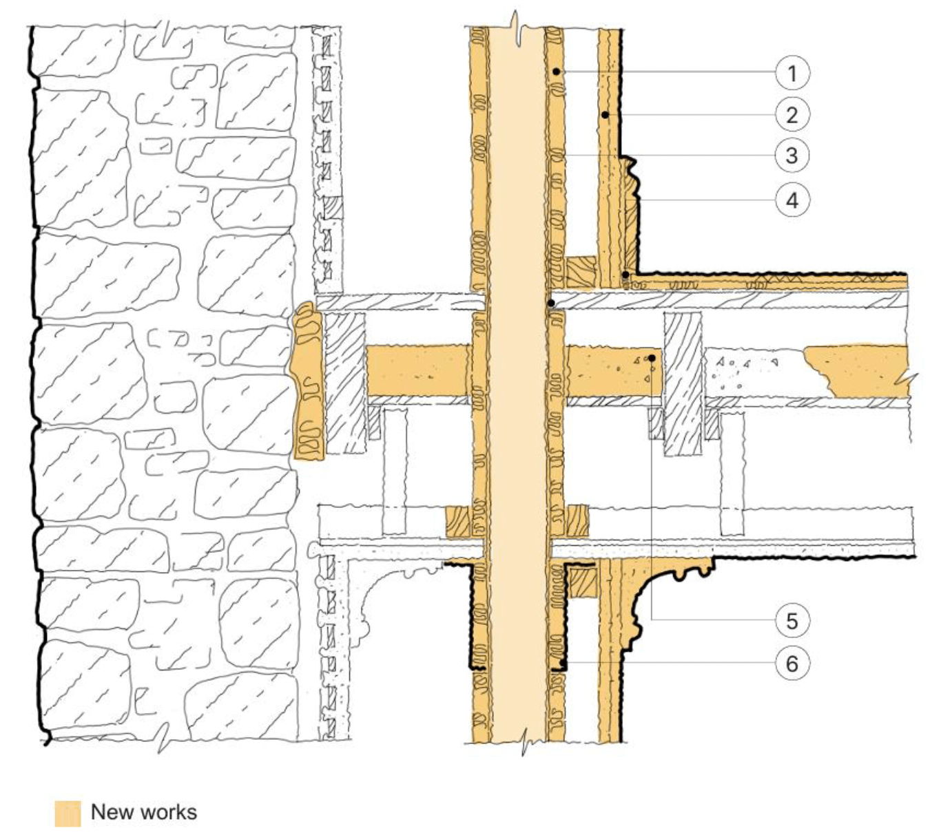
Illustration 82 provides example guidance on the acoustic lining and boxing to SVPs to reduce service noise and reduce flanking transmission via such services. Note the isolation of the resilient floor treatment from the perimeter walls and boxing by a shallow 5mm flanking strip. This reduces impact sound transmitting via the structure through the isolation at this junction.
Drawing notes:
1. SVP fully wrapped with 25mm (minimum) mineral wool quilt (10-36kg/m3) or equivalent.
2. Pipe boxed with a minimum of two layers of 15mm high density gypsum-based board (minimum 10kg/m2).
3. All voids around pipe sealed.
4. Minimum 5mm resilient flanking strip.
5. Fully backfill ash deafening or equivalent (see floor type 1 note 5).
6. Fire stop/collar.
Note: Refer to Section 2: Fire, for further guidance on ceilings and wall linings and Section 3: Environment, for ventilation of wall cavity voids.
Floor Type 2 – A traditional timber separating floor with a directly fixed lath and plaster ceiling to the joists (illustration 83).
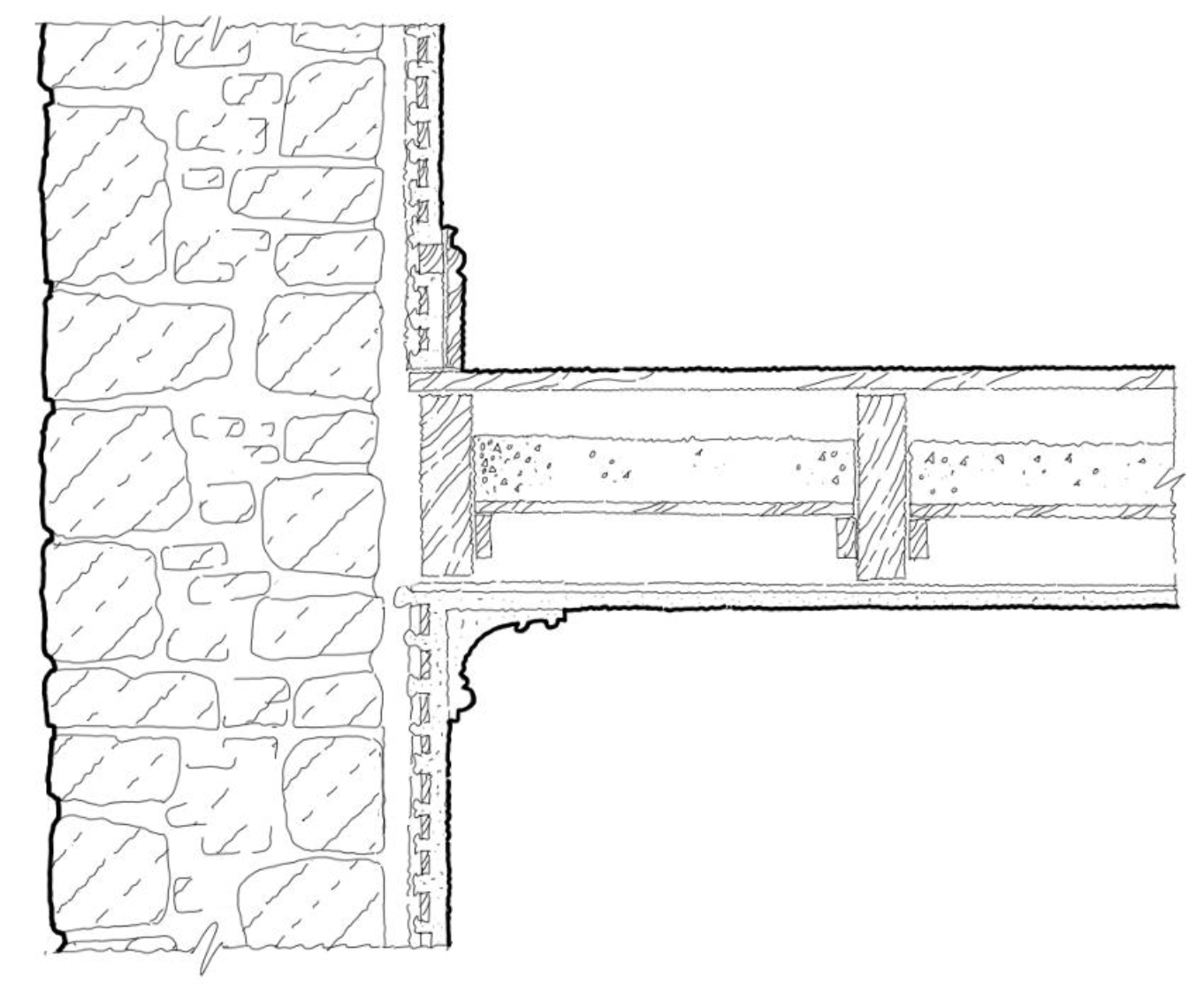
When Undertaking Remedial Work:
- Pay particular attention to the deafening where floor damage may have occurred (e.g. kitchens, bathrooms, along central heating and water service runs and perimeter voids).
- Ensure, where possible, that the lath and plaster ceiling is retained.
- Ensure patching of lath and plaster ceiling to be a minimum of 2 layers of high-density gypsum based boards (minimum 12.5mm at 10kg/m2).
- Ensure service ducts detailed through the Separating Floor are boxed with a timber or metal frame lined with minimum of 2 layers of 15mm high density gypsum-based board (minimum 12.5mm at 10kg/m2). Service pipes should also be wrapped with 25mm quilt insulation (minimum 10kg/m3). Voids in deafening around service runs to be made good in line with the guidance given for the insulation.
- Ensure gaps of over 25mm in ceiling or floor are packed with mineral fibre (minimum 10kg/m3) then sealed with caulk.
Note: Refer to Section 2: Fire, for further guidance on ceilings and wall linings.
Two options are provided involving upgrading by increased intervention using deeper floating floor surface treatments (Option 1) or by installation of a secondary suspended ceiling (Option 2).
Option 1 Illustration 84 – a floating floor treatment (isolating batten or resilient cradle system), where the floor level can be raised.
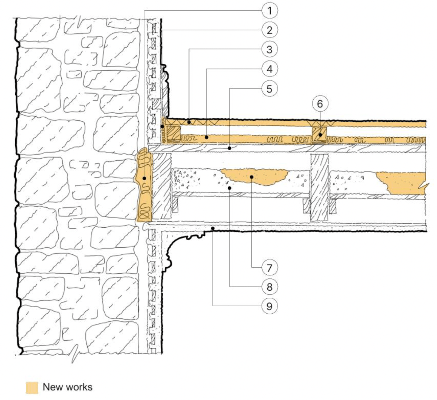
Drawing notes:
1. Minimum 33kg/m3 mineral fibre quilt packed into void at wall junction
2. Resilient flanking strip
3. 22mm chipboard flooring
4. 25mm (min) mineral fibre quilt between battens (minimum 10kg/m3)
5. Existing floor
6. Isolating batten or resilient cradle system. A minimum laboratory performance of ∆Rw=10dB and ∆Lw=13dB
7. Granular remedial treatment of similar density and depth to existing deafening: traditional ash (75mm), or 2-10mm limestone chips (60mm), or 2-10mm whin aggregate (60mm), or dry sand (50mm) Figures in brackets show approximate thickness required to achieve 80kg/m3
8. Ash deafening on deafening boards
9. Lath & plaster ceiling
Note: Refer to Section 2: Fire, for further guidance on ceilings and wall linings and Section 3: Environment for ventilation of wall cavities.
Notes for Option 1 (illustration 84):
1. The floor level has been raised due to the deeper floating floor installed and will present problems at internal doors, which will have to be reduced in height.
2. The entrance door to the flat will require a shallow ramp to be constructed inside the entrance to accommodate a possible difference in floor level between the common access and the flat (to support access).
3. The use of heavy-weight granular material between the joists will be possible only where the timber floor structure can carry the additional loads.
4. Sealing the junction between the wall and floor will reduce flanking sound transmission. However, there is potential to create stagnant air voids behind the plasterwork and skirting-level, where ventilation may have to be introduced to maintain a low level of air movement.
An example of acoustic linings for SVPs and junctions between deeper floating flooring treatments is shown in Illustration 85.
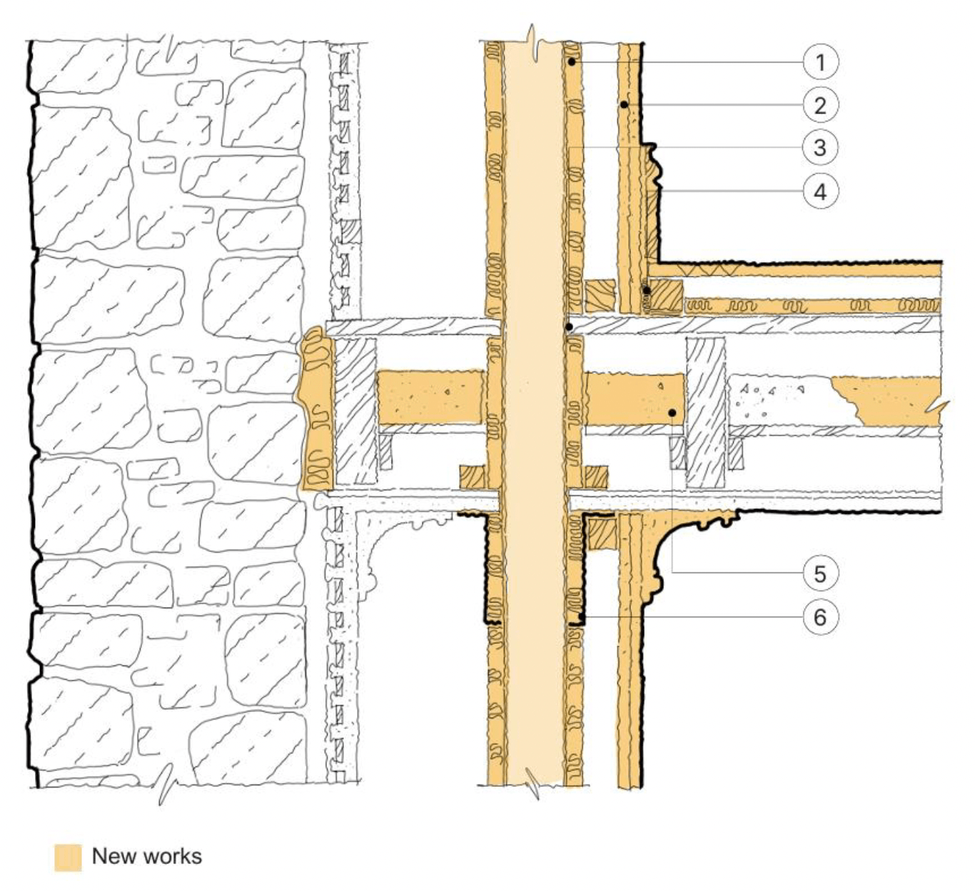
Drawing notes:
1. SVP fully wrapped with 25mm (minimum) mineral wool quilt (10-36kg/m3) or equivalent
2. Pipe boxed with a minimum of two layers of 15mm high density gypsum-based board (minimum 12kg/m2)
3. All voids around pipe sealed
4. 5mm (minimum) resilient flanking strip
5. Fully backfill ash deafening or equivalent (see floor type 1 note 5)
6. Fire stop/collar
Note: Refer to Section 2: Fire, for further guidance on ceilings and wall linings and Section 3: Environment, for ventilation of wall cavity voids.
Option 2 – (Illustration 86) upgrading using a suspended ceiling where an alteration to the floor level above cannot be accommodated.
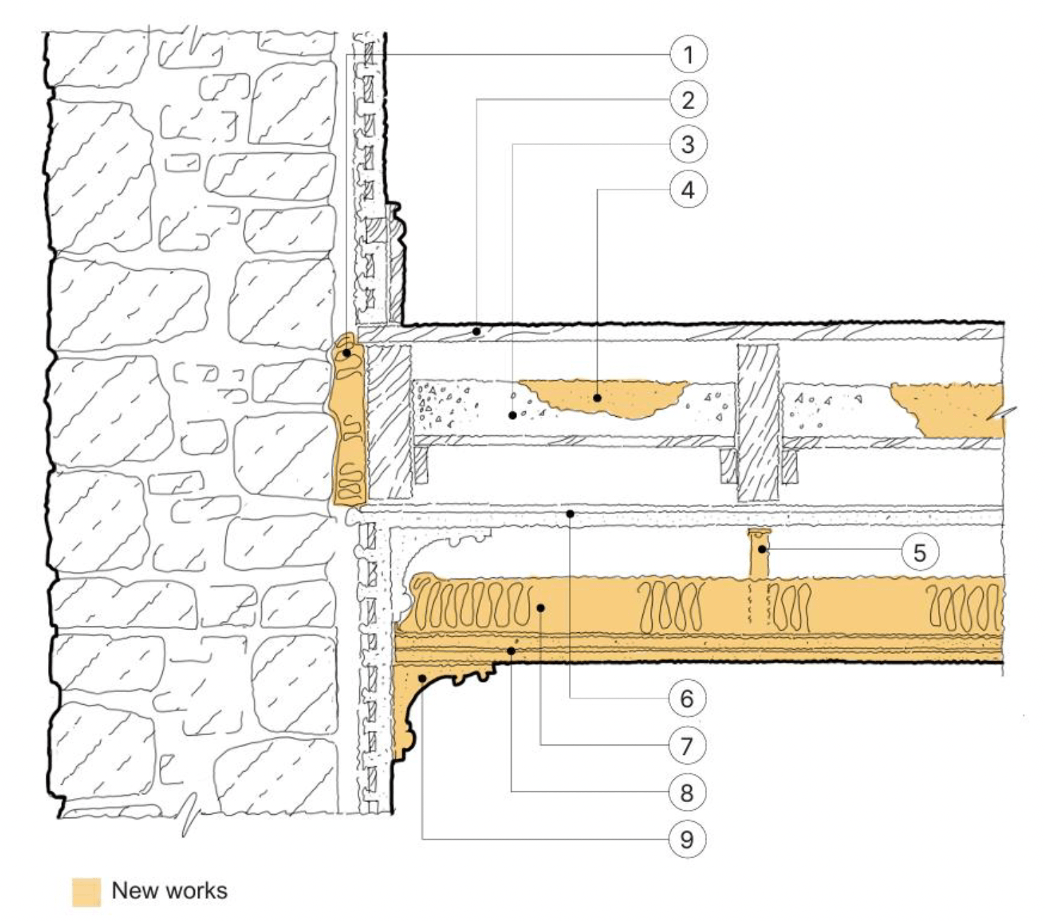
Drawings notes:
1. Minimum 33kg/m3 mineral fibre quilt packed into void at wall junction
2. Existing flooring
3. Ash deafening on deafening boards
4. Granular remedial treatment of similar density and depth to existing deafening: traditional ash (75mm), or 2-10mm limestone chips (60mm), or 2-10mm whin aggregate (60mm), or dry sand (50mm). Figures in brackets show approximate thickness required to achieve 80kg/m3
5. Suspended metal ceiling system to create a minimum cavity depth of 125mm or greater to enclose existing cornice
6. Lath & plaster ceiling
7. Minimum 100mm mineral fibre quilt (minimum 10kg/m3).
8. Two layers 15mm high density gypsum-based board (minimum 12kg/m2).
9. New cornice taken from a mould, or the original.
Note: Refer to Section 2: Fire, for further guidance on ceilings and wall linings and Section 3: Environment, for ventilation of wall cavity voids.
Notes for Option 2 (Illustration 86):
i. The existing ceiling is retained (where it is in good condition).
ii. The suspended ceiling system will reduce the floor to ceiling height.
iii. Existing plaster work to walls is reinstated and any feature cornice that has to be removed is replaced with a replica cornice, run in situ.
Option 2 should be adopted where an existing ceiling features ornate or original plasterwork that should be retained (but not visually). This allows a suspended ceiling to be used in which the existing ceiling, together with its important features, are preserved in situ but covered by a new ceiling below the cornice level, using an acoustic hanger support system fixed to the joists through the plaster lath.
While the original ceiling is lost from view, it remains in place and may be exposed at a later date should the use of the building change. However, such an approach would only be adopted where obscuring original plasterwork clearly has a benefit in terms of securing the wider building through its adaptation and re-use. In practical terms, this approach may only be possible where there is sufficient height between the head of a window opening and the cornice to accommodate the new ceiling. If a significant space with an important ceiling has rooms of less significance above it, it may be preferable to adopt Option 1 as a means of allowing the ceiling to remain visible so that it continues to add to the understanding and appreciation of the building.
2. Concrete separating floors
Methods of upgrading concrete separating floors are not often encountered in the conversion of traditional buildings, therefore no specific guidance on upgrading works is available. Carrying out a conversion is likely to be less disruptive to buildings which have concrete floors than it is for the conversion of other building types. In general, this is due to the higher mass of the core floor, greater floor-to-ceiling heights found in these buildings and, the utilitarian nature of their floors and ceilings.
Floors will generally have adequate airborne sound insulation, but improvements will be required to insulate against impact sound. Several options are available to improve impact performance:
1. Where there is a restricted floor-to-ceiling height, a shallow resilient floor overlay, as described in illustration 81, can be laid on the concrete floor surface. However, any gaps within the concrete floor construction must be sealed up, to reduce airborne transmission, before the overlay is installed.
2. Where the floor-to-ceiling height is not an issue, a floating floor, consisting of chipboard set on resilient battens as shown in illustration 84, may be constructed on top of the concrete slab. This is the preferred method and has the added advantages that the floor can be levelled, and services can be accommodated within the floor void. Impact resistance is also better than for the shallow resilient overlay system.
3. If the concrete slab does not provide the required level of airborne sound insulation, the installation of an acoustic ceiling system will be necessary, such as the lining ceiling system shown in illustration 86.
a) Upgrading to separating walls
Masonry separating walls that are less than 215mm in thickness, for example a half-brick wall plastered ‘on the hard’ or with lath and plaster (see Illustration 87), will not meet the required standard of minimum airborne sound insulation.
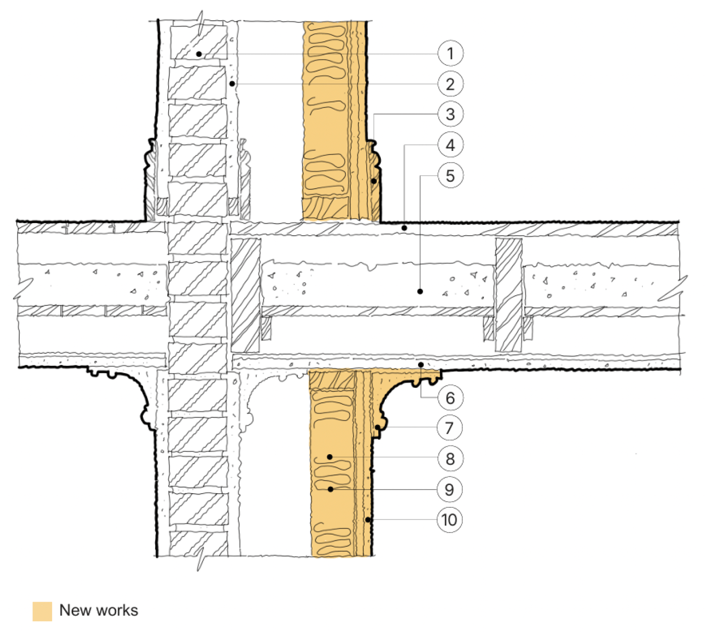
Drawing notes:
1. Half brick wall
2. Plaster finish
3. Replace skirting (leaving 5mm gap between skirting and floorboards)
4. Floorboards
5. Timber floor with ash deafening
6. Lath & plaster ceiling
7. New cornice taken from a mould of original cornice
8. Free standing 100mm timber or metal partition offset from the core wall by 50mm.
9. Minimum 90mm mineral wool insulation (minimum 30kg/m3) installed between studs
10. Two layers of gypsum-based board (minimum 11.5 kg/m2 per board layer)
An upgrading treatment to improve sound insulation would typically involve a free standing 100mm timber or metal partition offset from the core wall by 50mm. Mineral wool insulation (min 90mm) with a minimum density of 30kg/m3 should be installed between the studs. This is finished with two layers of gypsum-based board min. 11.5 kg/m2 per board layer. However, this type of solution will encroach into the room and result in loss of original finishes and features.
Masonry separating walls over one brick (215mm) in thickness will also require to be upgraded to meet the minimum airborne sound insulation performance, however these may not always require free standing partitions. Specialist advice should be sought on all separating walls from a specialist building acoustic consultant.
b) Blocking up an existing door
The door is to be retained as a feature, complete with all the original features, and the in-fill to the door opening on the other side is matched to the existing wall finish. The two layers of gypsum board should be min 11.5kg/m2 per layer. In this example the airborne test performance was 56 dB DnT,w.
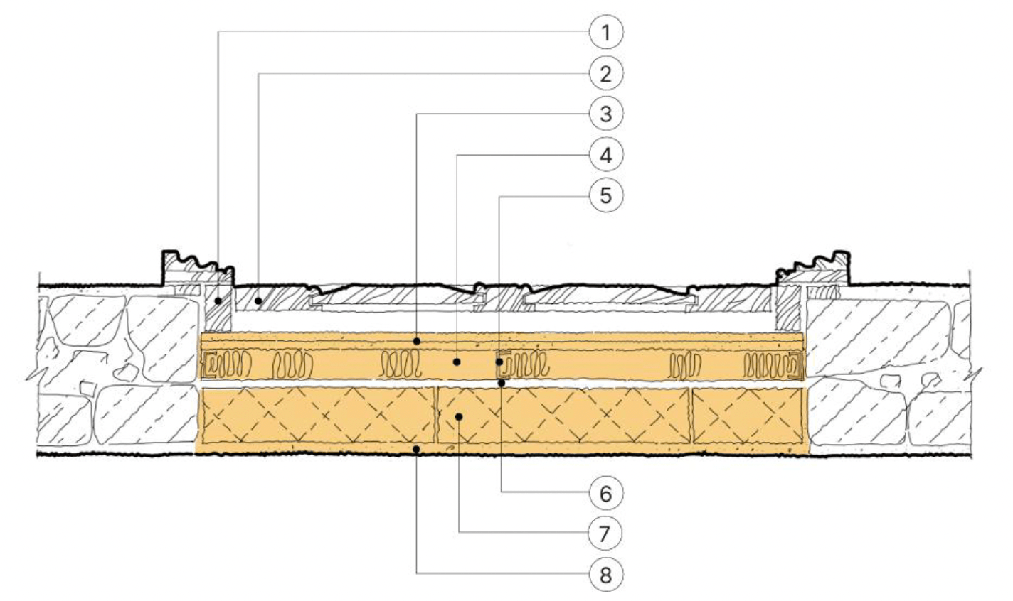
Drawing notes:
1. Original wall and door architrave
2. Original door retained
3. Two layers gypsum-based board
4. 50mm quilt
5. 48mm metal stud frame
6. 20mm cavity
7. 100mm dense block
8. 30mm plaster finish to match existing
Contact
Email: buildingstandards@gov.scot