Timber cladding in Scotland
The study outlines the development of timber cladding in Scotland, describes timber clad buildings in Scotland, and provides practical information on the use of timber cladding in Scotland.
Timber Cladding in Scotland
DRAINAGE
Any rainwater not deflected from the cladding will tend to be drawn down the wall by gravity. The volume of run-off increases with the height of the building, but the path of any run-off is not always straight down, since wind will tend to push the water sideways. While the external face of the cladding should be able to deflect most wind-driven rain, it must always be assumed that some water will penetrate through it. Detailing should enable this to drain down the cavity and out through unrestricted openings at the base. In the UK, the cavity width for drained and back-vented cladding is recommended to be at least 19mm (1). This is a minimum width and, in general, the principle is that the more open the cladding joints, the wider the cavity required.
A WELL DRAINED CAVITY BEHIND THE CLADDING
Water penetrating through cladding joints tends to run down the back surface of the boards where it can be intercepted and drained back to the outside. The cavity is maintained through the use of spacing battens and these should be designed to enable water to drain freely - battens are generally spaced at 600mm centres to give adequate support to most types of timber cladding. Where movement-prone timber (e.g. 'green' oak) is used, however, the spacing should be reduced to 400mm to provide additional support (3). Care should be taken to ensure that horizontal battens do not block cavity ventilation. This usually requires the use of separate counter battens behind the horizontal battens. The base of a drained cavity should always allow free drainage and airflow, and all openings into the cavity should be fitted with an insect mesh.
|
|
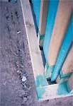
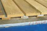
Watermarks indicate water is flowing down the back of the cladding during periods of driving rain. This should be allowed to drain away, but in this case the cavity has been closed at its base, with consequent potential for decay problems. |
Support battens create a well-drained cavity. Note the insect mesh at the base of the cavity. |
BREATHER MEMBRANES
A separate breather membrane is normally required behind the cavity, functioning both as an air seal to prevent wind penetration into the wall structure, and as a second line of protection against water penetration. Because of this dual role, the membrane should always be a high performance material not prone to tears or to wicking of moisture. TRADA (4) recommend that only membranes classed as Type 1 under BS 4016: 1997 be used.
FLASHINGS
Water flowing down the back surface of the cladding boards should be drained out of the wall assembly through the use of flashings. Poor flashing details are a major cause of moisture problems in timber cladding. One of the most common detailing mistakes is the failure to maintain a sufficient gap between the base of cladding boards and the flashing. This gap is vital for drainage, ventilation and to prevent the timber (particularly the endgrain) absorbing moisture due to contact with a wet, impermeable material. In the UK, this gap is recommended as 10 mm in most cases (3). Flashings may be needed at the base of walls, at storey height horizontal breaks, and above and below openings. Flashings should always be sloped to the outside and wherever one is interrupted it should have end dams to prevent water running off the ends.
WINDOW AND DOOR FLASHINGS
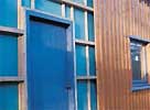
As with timber cladding, the detailing of windows and doors against wind-driven rain should always incorporate a two-stage approach in which the primary rain screen is separated from the secondary wind seal by a drained and vented cavity (5). The junction between the frame and the cladding should be protected behind a cover board (the 'check reveal') which overlaps the frame by 10-20mm (11). In this case, wooden window sills are insufficient to span the 80mm or more required to reach the outer surface of the cladding, and consequently separate sills are required which - in the case of a timber-clad building - are normally achieved through the use of metal flashings. It is easiest to achieve a wind and watertight seal around the window when the upper edge of sill flashings (where they tuck under the window frame) is flush with, or slightly outside of, the breather membrane that provides the air seal on the wall. Flashings around openings should project from the wall by a minimum of 50mm (5).
Detailing of flashings around openings requires particular care, and these details are poorly described in most UK literature. Norwegian and Canadian recommendations state that window sill flashings require vertical upstands of at least 20mm at the back and sides to control water leakage (5, 8). Both countries recommend corner joints be made waterproof. Flashings can be made from galvanised or stainless steel, copper, lead, aluminium or plastic and - depending upon the material - the corner junction could be waterproofed by welding, gluing with epoxy resin, folding without cutting, or the use of special end pieces. Gluing with silicon does not give long term protection (8, 1). The base of timber cladding boards forming the window jamb should be in front of, and overlap, the vertical upstand of the flashing. They should, however, be stopped so that the endgrain is separated from the flashing by a gap of at least 6mm in order to avoid endgrain take-up of moisture (5, 12).
These details describe best practice from a detailing-for-durability viewpoint. Unfortunately there appears to be a conflict in the Scottish Building Regulations between the need to maintain unrestricted cavity drainage above a window or door, and the requirement (under Part D of the regulations) to provide a cavity barrier around an opening. The intention behind this requirement is to restrict the spread of smoke and flame from the room of fire origin into the cavity and to restrict the fire spreading between cavities.
In the case of low-rise housing, the requirement for cavity barriers above openings in timber cladding may be relaxed in practice. This is probably because (providing other parts of the structural fire regulations are adhered to) the risk of fire spreading into the cavity is outweighed by the risk of timber decay due to inadequate cavity drainage (13). Where the requirement is relaxed then the accompanying window details are consistent with the detailing advice given here, however these details are not definitive and their use would need to be approved with local Building Control officers.
In some cases, cavity barriers above openings will be required and, where this occurs, the durability of the cladding assembly could be compromised. A possible solution to this problem is to use cavity barriers made from 50mm thick wire-reinforced mineral wool which should permit a minimum level of drainage and ventilation (13). Further research and guidance on this issue would be beneficial.
Schematic window details for use in exposed Scottish conditions.
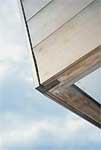
OVERSAILS
In many circumstances, an alternative to flashings is to ensure the cladding oversails the surface below. Once again, a suitable drainage and ventilation gap needs to be maintained.
AVOID HORIZONTAL SURFACES IN EXTERNAL TIMBER
Exposed horizontal, or near-horizontal, surfaces in external joinery such as windows or cladding drain slowly and therefore, prone to wetting, should be avoided or protected by a suitable flashing. Some species (e.g. oak) are particularly vulnerable because the timber is prone to staining if it remains wet for extended periods.
AVOID WATER TRAPS
Some types of detailing create watertraps which can lead to decay problems, and the use of diagonal cladding is particularly prone to this. Complicated or over-fussy detailing can also lead to problems and should be avoided in exposed maritime conditions - simple conventional details generally work best and have helped to inform the plain Scottish aesthetic
KNOT ORIENTATION
Many 19th century softwood-clad buildings in Scotland demonstrate a conscious attempt to arrange the boards so that the slope of the knots through the boards went upwards from the outside to the inside of the cladding assembly. This reduced the potential for water leakage through the knots. Assuming (to control movement problems) the heartwood side of the board closest to the pith is installed towards the outside of the building, the root-end of the board requires to be pointed downwards on the wall. Victorian buildings were erected in the days before rainscreen cladding design was introduced in Scotland, and so maintaining a leak-proof cladding was very important. This technique would have significantly reduced the amount of water able to penetrate the cladding, but with outer cladding nowadays drained and back-vented, this is less important. Nonetheless, it is still identified amongst the board grading options in current Norwegian recommendations (5). Such techniques are impossible with horizontal cladding boards (which may be slightly less durable as a result) and are not relevant to hardwood cladding because of the smaller number of knots.
|
drying The breather membrane providing the inner air seal should be kept as dry as possible. In principle, the provision of adequate ventilation behind the cladding will increase the capacity for drying and thus reduce the amount of water reaching the inner surface of the cavity. There are two schools of thought regarding the degree to which cavities should be vented at the top. In the UK and Norway it is recommended that a gap of 6mm be maintained at the top of a cladding cavity. This increases the volume of air passing through the assembly and thus the potential to dry the cavity through evaporation. Conversely, in British Columbia it is argued that venting the top of the cavity - particularly at the top of a high or exposed building - may result in a negative air pressure being created within the cavity which will tend to draw water into cavity from outside. Because of this risk, Canadians take the view that cavities should not be ventilated at the tops of walls (8). The main points to note are: |
Elm cladding oversails the brick plinth to provide a gap for drainage and ventilation. |
|
VENTILATION GAPS Providing there is an adequate drainage gap at the base of the cladding cavity, adequate ventilation will also exist. Following Norwegian experience, it is important that further ventilation is provided higher up the wall. This must happen at points where wind-driven rain does not reach. Depending upon the building design, such points generally include: below and above windows; at horizontal storey-height wall flashings; and under the roof overhang. Cladding of one storey-height or higher must be ventilated at the top and the bottom, whilst cladding over only part of a storey-height can be ventilated at the bottom only. In severely exposed areas, cladding should be detailed so that water can exit at each storey level. Where openings are not provided below windows, the air cavity requires connections to allow free air movement into the areas to the side which may otherwise be blocked by the vertical support battens (3, 5, 8).PROVIDING FOR SHRINKAGE AND EXPANSION ACROSS WIDTH OF BOARDS Timber cladding changes dimension slightly as it gains and loses moisture. For tongue and groove or other profiles that have little capacity to accommodate movement, the maximum board width recommended is 100mm, with 150mm the normally recommended maximum width for other boards (3, 5). Narrow boards are less prone to movement problems and, where tongue and groove boarding is to be used, the boards should be no more than 100mm wide. The tongue or overlap should always be of sufficient width to accommodate possible shrinkage without becoming disengaged. Generally, tongue-widths should not be less than 9mm, and commercial profiles which provide tongue-widths of 6mm or less should be avoided. Board-on-board designs are the most suitable where boards over 100mm are being used, though, providing there is sufficient thickness, a 20mm rebated overlap may be used on boards up to 150mm width. To minimise water penetration through the joints 100-150mm wide cladding boards normally need to be detailed with joint overlaps of 15-25mm. A 2mm expansion gap should normally be provided between all cladding boards. Board thicknesses are between 16-22mm depending on the profile used. |
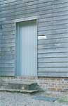
Vertical cladding installed below a window opening.Note: The rear board has been coated before installation to allow for subsequent shrinkage of the outer board. The outer board is installed so that the inner heartwood side of board is facing outwards on the building. The boards have good overlaps. The fixings have been placed so as to avoid going through both overlapping boards. Counter battens are not generally needed with this type of cladding is there is adequate ventilation behind the outer board. |
Where possible, cladding should always be installed so that the inner heartwood side of the board is facing outwards on the wall, thereby minimising movement problems should the boards dry out in-situ. Where board-on-board designs or rebated overlaps are used, nailing through two overlapping boards should always be avoided as this restricts board movement and increases the danger of splitting (3. 5).
When used as cladding, green oak (i.e. unseasoned oak) will shrink by at least 7% across the board width as the timber dries. During the first year this can equate to 10mm or more over a 150mm wide board. Detailing needs to accommodate this and the options include overlapping boards, oversize holes around fixings, and open jointed designs.
SUPPORTING BOARDS ADEQUATELY
Boards are fixed to support battens to create a drained and ventilated cavity. A continuous air gap is essential and, with vertical cladding, counter battens will usually be needed to ensure cavity ventilation is maintained. Some types of board-on-board claddings have a sufficient gap behind the outer board and, in such cases, counter battens may not be needed on moderately sheltered sites. In the UK, no more than 600mm between support battens is recommended. However, where very movement-prone timber (e.g. unseasoned green oak) is used, this distance should be reduced to 400mm (3).
COATING BOARDS BEFORE FIXING
If boards are to be given a coating, the primer and at least one top-coat should be applied before they are fixed to the wall. This avoids the problem of boards shrinking in-situ and exposing uncoated surfaces. It is also desirable to coat the rear of boards at the same time as this reduces the risk of wetting due to water running down the inside of the cavity.
DURABILITY
Timber cladding can become saturated during periods of driving rain. Moreover, the high rainfall and relatively mild climate in parts of Scotland can lead to very high levels of relative humidity occurring, particularly in the winter months. Consequently, although cladding assemblies may be well drained and vented, there may still be a risk of the timbers being damp for extended periods. In such circumstances there may be an increased risk of fungal decay and insect attack whenever the temperature is warm enough. There are also corrosion risks with ferrous metals and aluminium, as well as weathering risks due to moulds and UV light. The two main durability points to remember are:
2At moisture contents above 20% all timbers are acidic due to the breakdown by water of wood cellulose into acetic acid. No wood species is immune to this process and, as a result of the corrosive effect of acetic acid, both mild steel and galvanised mild steel fixings can cause unsightly staining on timber cladding. More corrosion resistant materials such as stainless steel are preferable for embedded fixings and should always be used with uncoated cladding. Stainless steel fixings are readily available from specialist suppliers. Only austenitic stainless steels have sufficient corrosion resistance for use in cladding, with type 1.4301(304) stainless steel recommended for most cladding applications, and the more durable type 1.4401(316) recommended for coastal sites(14) . Non-ferrous fixings such as silicon bronze could also be used and are sometimes supplied with western red cedar cladding. They are also readily obtainable from marine chandlers.
|
|
|
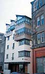
A durable timber such as European oak or imported western red cedar is essential in situations where maintenance would be prohibitively expensive. |
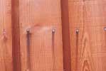
Galvanised steel fixings are not suitable for use with uncoated external timber cladding - only two weeks after galvanised steel fixings were embedded in unseasoned European larch cladding, unsightly black stains have occurred. |
Because the support battens behind the outer cladding are difficult to replace, they should always be preservative-treated or be of moderately-durable timber. |
References
1 National Building Specification, 2000, Timber Weatherboarding.
2 E & F Spon, 1992, Component Life Manual.
3 Hislop, P., 2000, External timber cladding, TRADA Technology
4 TRADA, 2000, Breather membranes for timber frame walls.
5 Byggforsk, 1998, Byggforsk kunnskapssystemer ver 1.0, Norwegian Building Research Institute,
6 Hamilton, et al., 1993, The Scottish Building Regulations Explained and Illustrated, Blackwell Scientific Publications
7 Blass et al., Ed. 1998, Timber Engineering - STEP/Eurofortec Vol 1, Centrum Hout.
8 Canada Mortgage and Housing Association, 1999, Wood-Frame Envelopes in the Coastal Climate of British Columbia.
9 Canada Mortgage and Housing Association , 1996, Survey of Building Envelope Failures in the Coastal Climate of British Columbia.
10 Dept of the Environment, 1995, Energy Efficiency in New Housing, External Cavity Walls, HMSO
11 Dept of the Environment, 1993, Energy Efficiency in New Housing, Windows and External Doors; HMSO.
12 Hislop, P., Wood windows, TRADA, 1993.
13 The Swedish Finish Timber Council, 1982, Exterior Cladding of Redwood and Whitewood
14 Stainless Steel Advisory Service, 2000, Austenitic Stainless Steel for Timber Fixings.
British Standards
BS 1186-3: 1997. Timber for and workmanship in joinery.Specification for wood trim and its fixing.
BS EN 350-2: 1994. Durability of wood and wood basedproducts - Natural durability of solid wood - Guide to the natural durability and treatability of selected wood species of importance in Europe.
BS EN 460: 1994. Durability of wood based products. Natural durability of solid wood. Guide to the durability requirements for wood to be used in hazard classes.
DD 239: 1998. Recommendations for the preservation of timber.
BS 4016: 1997, Specification for flexible buildingmembranes (breather type).
Contact
Email: Central Enquiries Unit ceu@gov.scot