Calculating carbon savings from wind farms on Scottish peat lands: a new approach
This approach was developed to calculate the impact of wind farm developments on the soil carbon stocks held in peats. It provides a transparent and easy to follow method for estimating the impacts of wind farms on the carbon dynamics of peat lands.
7. Recommended revised method for calculating carbon dynamics from peat lands
A concise approach has been produced describing the response of changes in soil C stocks and greenhouse gas emissions to peat removal and drainage. This provides a transparent and easy to follow method for estimating the impacts of wind farms on C dynamics on peat lands and is described below.
A full, life-cycle based calculation of C payback time has also been developed and is included in Appendix 2. This approach looks at much wider issues such as carbon used to make and transport turbines and backup generation and may be useful for comparing with other energy sources on the same basis in the future.
Modifications included in ver 1.0.6 (pdf)
7.1. Change in carbon dynamics of peat lands
Peat lands (which include mires, fens, bogs and other wetlands associated with peat land) contain huge reservoirs of C. Globally, they represent over one-third of the C in all soils Hargreaves et al., 2003). The total amount of C held in organic soils in Scotland is 2735 Mt C, with 1778 Mt C being held in peats (including blanket peats, basin peats, and semi-confined peats; Smith et al, 2007). In their undisturbed state, peat lands emit the greenhouse gas CH 4, but accumulate C derived from the atmosphere. Emissions of the greenhouse gas nitrous oxide are usually negligible in unfertilised peat lands ( IPCC, 1997). Overall, peats represent a large reservoir of CO 2 captured by plants and held in soils. The first step in the accumulation of C in soil is sequestration from the atmosphere by vegetation through photosynthesis. The second step is storage in soil organic matter. Organic matter accumulates primarily in response to anaerobic, waterlogged conditions and low potential for decomposition either through temperature or acidity constraints in the soil. Wind farm development on peat lands will result in a change in the C dynamics by changing the C inputs and altering peat land hydrology, which affects soil organic matter turnover. This approach calculates both the direct and indirect impacts of a wind farm development on the C dynamics of peat lands. Changes in C due to habitat improvement and site restoration are also included to give a holistic measure of the effect of wind farm development on the C dynamics of peat land.
7.2. Loss of carbon fixing potential of peat lands
The development of a wind farm requires the construction of infrastructure such as turbine foundations, crane hard standings, access tracks and works compounds. Generally, peat is removed from these areas and as a result there is a loss of the C fixing potential of the associated vegetation. During construction and operation of a wind farm, the soil may be drained by design or unintentionally. Drainage has significant effects on the vegetation of peat lands (Stewart and Lance, 1991). Here, the loss of the C fixing potential of the peat land is calculated for the area from which peat is removed and also for the area affected due to drainage.
The estimated global average for the apparent C accumulation rate in peat land ranges from 0.12 to 0.31 t C ha -1 yr -1 (Turunen et al., 2001; Botch et al., 1995). If it is available, site specific data can be used. However, this loss represents a very small proportion of the total emissions, so the mid-range value used in the previous guidance (0.25 t C ha -1 yr -1 = 0.92 t CO 2 ha -1 yr -1) provides an adequate estimate. Loss of C fixing potential of peat land, L fix (t CO 2), is calculated from the area affected by wind farm development (both directly by removal of peat, Adirect (ha), and indirectly by drainage Aindirect (ha)), the annual gains due to the C fixing potential of the peat land, Gbog ( Gbog = 0.92 t CO 2 ha -1 yr -1), and the time required for habitat restoration, trestore (years).
![]()
7.3. Changes in carbon stored in peat lands
This C represents the greatest risk in terms of potential loss of CO 2 because peat takes a long time to accumulate in temperate regions and hence site restoration and C savings need to reflect this. During wind farm construction, C is lost directly from the excavated peat and indirectly from the area affected by drainage. The potential impact of peat removal is estimated from the volume of peat removed by different practices. Loss of C from the excavated peat is assumed to be 100%. If the excavated C is later restored, so potentially reducing the C losses from excavated peat, it is added to the area and depth of the improved site. This allows good peat preservation practices to be accounted for in the C emission savings. Indirect loss of C due to drainage is estimated using default values from the Intergovernmental Panel on Climate Change ( IPCC, 1997) as well as by more site specific equations derived from the scientific literature (Smith et al., 2007, Nayak et al., 2008). Carbon gains due to habitat improvement are similarly estimated using IPCC default values ( IPCC, 1997) and the more site specific equations derived from the scientific literature (Smith et al., 2007, Nayak et al., 2008).
7.3.1. Loss of carbon from removed peat
The total volume of peat removed during construction, Vdirect (m 3), is calculated from the dimensions of structures introduced to the site during development (average length, li (m), width, wi (m), and depth, dpeat,i (m) of each construction, i). Borrow pits, turbine foundations, hard-standing area and access tracks are currently included in the spreadsheet.
![]()
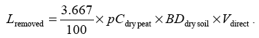
The total area of peat removed, Adirect (m 2), is calculated similarly using average length and width. Loss of C from the removed peat, Ldirect (t CO 2), is assumed to be 100%. If peat is later returned to the site with full restoration of the habitat and hydrological conditions, the volume of restored peat is added to the calculation of C emission savings due to site improvement. However, for this option to be used, the restoration plan should demonstrate a high probability that peat hydrology will be restored and disturbance of peat minimised. Loss of C from the removed peat, Lremoved (t CO 2), is calculated from the C content of dry peat, pCdrypeat (%), the dry soil bulk density (dried to a constant weight at 105° C), BDdrysoil (g cm -3), and the volume of peat removed, Vdirect (m 3),
When flooded, peat soils emit less CO 2 but more CH 4 than when drained. In flooded soils, CO 2 emissions are usually exceeded by plant fixation, so the net exchange of CO 2 with the atmosphere is negative and soil C stocks increase. When soils are aerated, CO 2 emissions usually exceed plant fixation, so the net exchange of CO 2 with the atmosphere is positive. To calculate the C emissions attributable to removal of the peat only, Ldirect (t CO 2 eq.), any emissions occurring if the soil had remained in situ and undrained are subtracted from the emissions occurring after removal,
![]()
7.3.2. Loss of carbon from drained peat
Estimation of volume of peat affected by drainage
The extent of drainage around the site of construction strongly influences the total volume of peat impacted by the construction of the wind farm. Where sufficient measurements are available to describe the hydrological features of the wind farm area, this should be used together with a detailed hydrological model to simulate the likely changes in peat hydrology. If insufficient measurements are available, a worst case estimate of extent of drainage around the development features should be used.
The volume of peat affected by drainage is calculated assuming the additional drained zone of edrain (m) on each side of the construction. Note that the area where peat is removed should not be included because C loss from removed peat has already been counted in direct losses. The calculation of volume affected by drainage, Vindirect,i (m 3), uses the extent of drainage, edrain (m), average length, li (m), width, wi (m), and depth of drainage, ddrain,i (m) for each construction feature, i.
For borrow pits, and turbine and hard-standing foundations, the depth of drainage, ddrain,i (m), is assumed to be equivalent to the depth of the construction. The calculation uses the following equation,
![]()
The volume drained around switching stations, site compounds and lay-down areas can be calculated similarly. If permanent drainage around foundations and hard-standing is not required, the area should be assumed to be drained only up to the time of completion of backfilling, removal of any temporary surface drains, and full restoration of the hydrology.
For access tracks, the depth of any drainage and the area included is dependent on the type of track. For excavated and rock-filled roads, the depth of drainage, ddrain,i (m), is assumed to be equivalent to the depth of the track. The peat removed or displaced by construction of the track is not included in the drained volume. The volume affected by drainage is calculated using the following equation,
![]()
The volume affected by drainage around cable trenches with permeable linings ( e.g. sand) that deviate from the lines of tracks should also be calculated using the above equation.
For floating roads, drainage is only included for the length of track that has been specifically drained, and the depth of drains is taken to be as specified for the drains. Since, in many cases, floating roads are known to sink, evidence should be provided about the risk of requirements for additional drainage. The volume affected by drainage is calculated using the following equation,
![]()
The total volume of peat affected by drainage, Vindirect (m 3), is the sum of the volumes of peat affected around each type of construction, Vindirect,i (m 3),
![]()
The total area of peat affected by drainage, Aindirect (m 2), is calculated similarly from the length and width of constructions and the estimated extent of drainage.
Loss of carbon from drained peat if the site is not restored after decommissioning
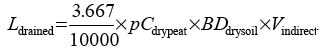
When flooded soils are drained, loss of soil C continues until a new stable state is reached. For peats, this is close to 0% C ( IPCC, 1997). Therefore, if the site is not restored after decommissioning of the wind farm, it is assumed that 100% of the C will be lost from the drained volume of soil. The loss of C from the drained peat, Ldrained (t CO 2), is calculated from the C content of dry peat, pCdry peat (%), the dry soil bulk density (dried to a constant weight at 105° C), BDdry soil (g cm -3), and the volume of peat drained, Vindirect (m 3),
Loss of carbon from drained peat if the site is restored after decommissioning
Restoration of the site could potentially halt C loss processes, allowing CO 2 emissions to be limited to the time before the habitat and hydrological conditions are restored. The amount of C lost is then calculated from the annual emissions of CH 4, ECH4 (t CO 2 eq. ha -1 yr -1), and CO 2, ECO2 (t CO 2 ha -1 yr -1), the area of drained peat, Aindirect (ha), and the time until the site is restored, t (years). However, for this option to be used, the restoration plan should demonstrate a high probability that peat hydrology will be restored across the site (water table at the surface for over 50% of the year), disturbance of the remaining peat will be minimised, and peat forming vegetation will develop in areas from which peat was removed or drained. If restoration of the site is inadequate, the amount of C lost will be in between the range of values calculated for restored and non-restored sites.
Methane emissions are calculated using the following equation,
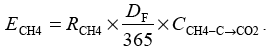
where ECH4 is the total annual emissions of CH 4 (t CO 2 eq. ha -1 yr -1), RCH4 is the annual rate of CH 4 emissions (t CH 4-C ha -1 yr -1), DF is the number of days in the year that the land is flooded, and CCH4-C? CO2 converts CH 4-C to CO 2 equivalents ( CCH4-C? CO2 = 30.67 CO 2 eq. (CH 4-C) -1).
Carbon dioxide emissions are calculated using the following equation,
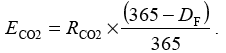
where ECO2 is the total annual emissions of CO 2 (t CO 2 ha -1 yr -1), RCO2 is the annual rate of CO 2 emission (t CO 2 ha -1 yr -1), DF is the number of days in the year that the land is flooded.
The total loss of C from the peat before drainage, Lundrained (t CO 2 eq.), is calculated from the annual emissions of CH 4, ECH4 (t CO 2 eq. ha -1 yr -1), the annual emissions of CO 2, ECO2 (t CO 2 ha -1 yr -1), the area to be drained, Aindirect (ha), and the time to restoration (assumed to be the life time of the wind farm), t (years),
![]()
The total loss of C from the drained peat, Ldrained (t CO 2 eq.), is calculated, using the same equation, but calculating the annual emissions of CO 2, ECO2 (t CO 2 ha -1 yr -1) and CH 4, ECH4 (t CO 2 eq. ha -1 yr -1) for a drained soil. Methane emissions will be negative or close to zero due to oxidation of CH 4 by the soil,
![]()
Peat soils emit less CO 2 but more CH 4 when flooded than drained. In flooded soils, CO 2 emissions are usually exceeded by plant fixation, so the net exchange of CO 2 with the atmosphere is negative and soil C stocks increase. In drained soils, CO 2 emissions usually exceed plant fixation, so the net exchange of CO 2 with the atmosphere is positive. To calculate the C emissions attributable to drainage only, Lindirect (t CO 2 eq.), any emissions occurring if the soil had remained undrained are subtracted from the emissions occurring after drainage,
![]()
The annual emissions of CH 4 and CO 2 can be estimated either using the IPCC default methodology ( IPCC, 1997), or using more site specific equations derived from the scientific literature (Nayak et al., 2008).
Calculation of changes in methane and carbon dioxide emissions from drained peat based on IPCC Guidelines. The IPCC default factors for acid bogs and fens in cool temperate zones are given in table 7.3.1. When the soil is undrained, the period of flooding is based on the monthly mean temperature and the length of inundation. When the soil is drained, the period of flooding is assumed to be zero (D F = 0 days yr -1).
Table 7.3.1.IPCC default emission factors used to calculate methane and CO 2 emissions
| Factor |
Acid Bogs |
Fens |
|---|---|---|
| Number of days in the year that land is flooded, DF |
178 |
169 |
| Annual rate of CO 2 emissions from drained soils, RCO2 (t CO 2 ha -1 yr -1) |
35.2 |
35.2 |
| Annual rate of CH 4 emissions from flooded soils, RCH4 (t CH 4-C ha -1 yr -1) |
4.015 x 10 -2 |
0.219 |
These are widely accepted, generic emission factors, but the figures are averaged across cool temperate peat lands and allow no use of site specific information, such as water table depth before wind farm development. Under the impacts of climate change, or if the site is not a intact peat land, the water table depth may already have been lowered before any drainage associated with the development. In this case, it is recommended that the more site specific factors given below are used as described in the next section.
Calculation of changes in methane and carbon dioxide emissions from drained peat using site specific equations. Methane emissions are calculated using the site specific equation described by Nayak et al. (2008), as shown below,

where RCH4 is the annual rate of CH 4 emissions (t CH 4-C (ha) -1 yr -1), T is the average annual air temperature (° C), pH is the soil pH and dwater is the water table depth (m). This equation was derived from 40 experiments on acid bogs and fens (see table 6.5.2), and has an associated R 2 value of 52.7%, P <0.0001. By statistical convention, if P<0.01 this relationship can be considered to be highly significant.
Carbon dioxide emissions are calculated using the site specific equation described by Nayak et al. (2008), as shown below,

where RCO2 is the annual rate of CO 2 emissions (t CO 2 (ha) -1 yr -1), T is the average annual air temperature (° C), dpeat is the peat depth (m) and dwater is the water table depth (m). This equation was derived from 41 experiments on acid bogs and fens (see table 6.5.2), and has an associated R 2 value of 53.8%, P <0.0001. By statistical convention, if P<0.01 this relationship can be considered to be highly significant.
The experimental data used to derive the above equations were collated during the development and evaluation of the ECOSSE model (Smith et al., 2007). Note that further improvement in a site specific estimate of CH 4, CO 2 and dissolved organic C losses could be obtained using measurements taken at the site to run a peer-reviewed and proven model of C dynamics, such as ECOSSE.
7.3.3. Loss of carbon dioxide due to leaching of dissolved and particulate organic carbon
Lowering the water table by drainage may reduce the potential for dissolved and particulate organic C retention within the soil ( e.g. Holden et al., 2004; Worrall et al., 2004) as well as increasing the decomposition rates (due to increased aeration). A recent study by Wallage et al. (2006) confirms that losses of dissolved organic C are higher from drained than undrained peats. Losses of CO 2 due to leaching of dissolved organic C, LDOC (t CO 2), are calculated by multiplying the sum of the gaseous losses of C from the different sources in the soil, Lgas (t C), by the percentage of the total gaseous loss of C that is leached as dissolved organic C, pDOC (%), and the percentage of leached dissolved organic C that is emitted as CO 2,pDOC? CO2 (%),
![]()
Losses due to leaching of dissolved organic C are assumed to be 10% of total gaseous C loss from the drained, restored and improved habitat peat land ( pDOC = 10) following the work of Dillon and Molot (1997) and Worrall et al. (2003). It is assumed that 100% of the dissolved organic C is emitted as CO 2 ( pDOC? CO2 = 100). Losses of particulate organic matter are calculated similarly, assuming the percentage loss is less than 15% of the total gaseous carbon losses after Worrall et al. (2003). Dissolved organic carbon can present a problem for water quality where costs for removal by water companies can be significant.
7.3.4. Loss of carbon due to peat slide
The Scottish Executive (2006) has established a rigorous procedure for identifying existing, potential and construction induced peat landslide hazards. This should lead to reduced likelihood of peat landslides occurring. It is assumed that required measures required to avoid peat landslides have been taken, so that the risk of peat landslide is minimal. Therefore this potential source of C loss is omitted from the calculations. Note that less catastrophic erosion losses, such as due to collapse of gullies, are not covered by the procedures to reduce peat landslides.
7.4. Loss/saving of carbon due to forestry clearance
The presence of extensive areas of forestry on and in the vicinity of the wind farm site can significantly reduce the yield of wind energy, so it has often been the practice to clear existing forestry from the area surrounding the site prior to wind farm development. The cleared land has then often been left as open ground. However, to reduce the long term loss of woodland alternative approaches should always be considered - such as 'key-holing' combined with replacing felled trees with short rotation coppice/ short rotation forestry or low-height native woodland, The losses of carbon from tree biomass depend on the fate of wood products following felling. Forestry may be felled earlier than planned due to the wind farm development, so limiting the nature and longevity of wood products. If a forestry plantation was due to be felled with no plan to replant, the effect of the land use change is not attributable to the wind farm development and should be omitted from the calculation. If, however, the forestry is felled for the development, changes in timber, residues and changes in soil conditions are attributable to the wind farm and should be accounted for.
The amount of C loss from timber and residues depends on the type of tree, the age of crop on felling, the end use of the timber and how quickly any stored C is returned to the atmosphere (Cannell, 1999). Cannell (1999) provides estimates for the amounts of C sequestered by fast growing trees (~26 yr rotation - e.g. poplar), medium (ï¾ 55 yr rotation - e.g. Sitka spruce), and slow growth (ï¾ 92 yr rotation, e.g. beech) (Table 7.4.1).
Table 7.4.1. Carbon sequestration for different species of tree
| Poplar |
Sitka |
Beech |
|
|---|---|---|---|
| Yield Class (m 3 ha -1 yr -1) |
12 |
16 |
6 |
| Carbon sequestered, G forest (t CO 2 ha -1 yr -1) |
26.8 |
13.2 |
8.8 |
| Crop rotation, t forest (years) |
26 |
55 |
92 |
| CO 2 sequestered per crop rotation (t CO 2 ha -1) |
694.66 |
724.68 |
808.86 |
Loss of CO 2 due to forestry clearance, Lforest (t CO 2) is obtained from the area of forestry to be felled, Aforest (ha), the average C sequestered per year, Gforest (t CO 2 ha -1 yr -1) and the lifetime of the wind farm, t (years),
![]()
European forest soils contain approximately the same amount of C as is found in tree biomass (Smith et al., 2006). Managed arable and grassland soils store significantly less C than soils under forestry or semi-natural management (Smith et al., 2005; Smith et al., 2006). The change in soil C stocks on tree removal will depend on subsequent land management, especially the drainage regime. These are calculated as described above.
7.5. Carbon dioxide saving due to improvement of peat land habitat
Habitat improvement at disturbed sites can significantly impact C emissions, potentially preventing further losses and increasing C stored in the improved habitat. Carbon gains due to habitat improvement are estimated using IPCC default values ( IPCC, 1997) and site specific equations derived from the scientific literature. Emissions of nitrous oxide are assumed to be negligible in unfertilised peat lands ( IPCC, 1997). However, for this option to be used, the improvement plan should demonstrate a high probability that peat hydrology will be restored and disturbance of peat minimised, resulting in rapid decolonisation of the natural vegetation.
To calculate the C emissions attributable to improvement only, Limprovement (t CO 2 eq.), any emissions occurring if the soil had remained drained are subtracted from the emissions occurring after flooding (negative, indicates a net reduction in emissions),
![]()
7.6. Soil and plant carbon losses and gains calculator
The full carbon calculator for wind farms on peat lands can be obtained from the following hyperlink: http://www.scotland.gov.uk/WindFarmsAndCarbon.
The worksheets are shown below.
7.6.1. Instructions Worksheet
This worksheet provides descriptions of all worksheets contained in the calculator. Full explanation of the calculations and assumptions are included in colour coded boxes (green boxes provide notes and blue boxes list assumptions).
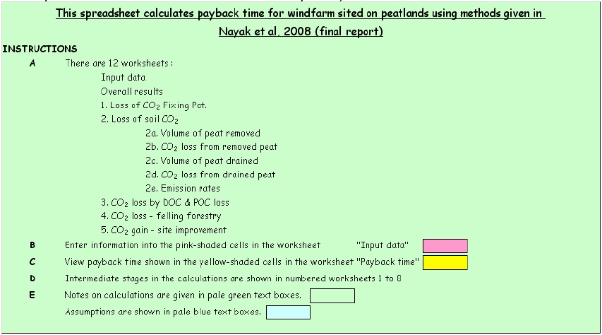
Figure 7.6.1. Instructions Worksheet
7.6.2. Worksheet for input data
All data are entered through a single worksheet. Data are grouped according to category.
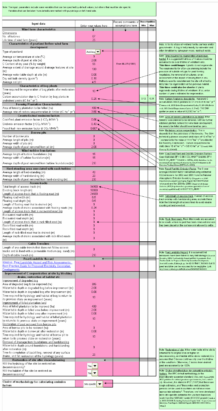
Figure 7.6.2. Worksheet for data input
7.6.3. Results Worksheet
Results are presented in terms of carbon emissions, in CO 2 equivalents, and as the C payback time associated with emissions from plants and soil only.
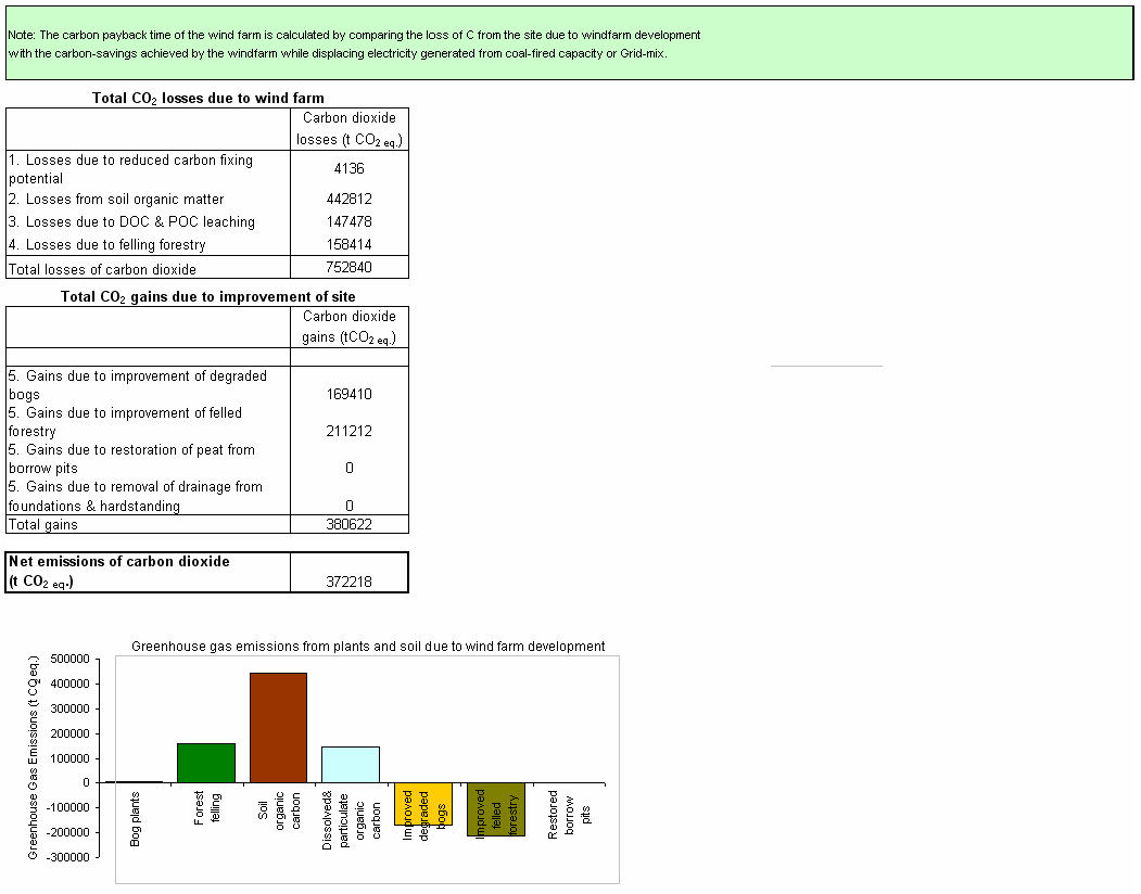
Figure 7.6.3. Results Worksheet
7.6.4. Loss of carbon fixing potential of bog plants
The loss of carbon fixing potential of bog plants is calculated assuming 100% loss of bog plants from removed and drained peats.
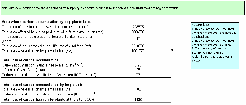
Figure 7.6.4. Loss of carbon dioxide fixing potential of bog plants
7.6.5. Total loss of soil carbon dioxide from the soil
The total emissions from the soil in CO 2 equivalents is calculated as the sum of losses from removed and drained peats.
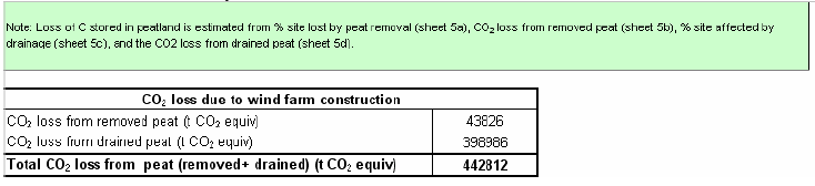
Figure 7.6.5. Total loss of carbon dioxide from the soil
7.6.6. Volume of peat removed
The volume of peat removed is calculated from the area and depth of peat associated with constructed features at the site.
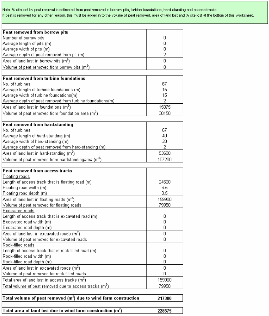
Figure 7.6.6. Volume of peat removed
7.6.7. Carbon dioxide loss from removed peat
Carbon dioxide losses from removed peat are initially calculated assuming the peat is not restored. The reduced losses from restored peat are later added back on in the worksheet describing restoration.
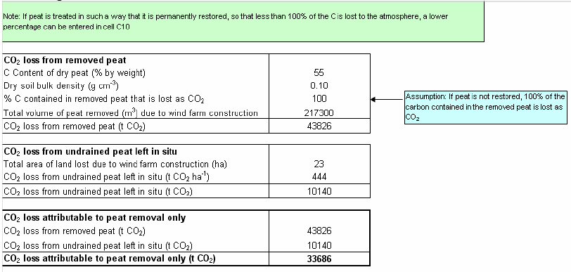
Figure 7.6.7. Carbon dioxide losses from removed peat
7.6.8. Volume of peat drained
The volume of peat drained is calculated using the extent of the area affected by drainage around each drainage feature.
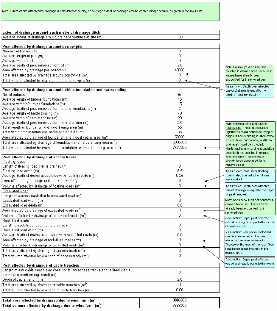
Figure 7.6.8. Volume of peat drained
7.6.9. Carbon dioxide loss from drained peat
Carbon dioxide losses from drained peat are calculated differently, depending on whether the site is restored and the water table returned to its original depth on decommissioning.
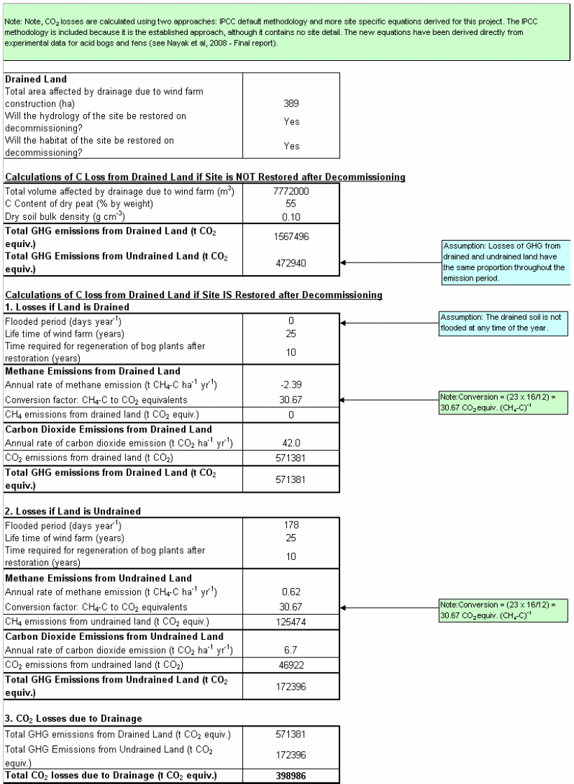
Figure 7.6.9. Carbon dioxide loss from drained peat
7.6.10. Emission rates from soils
Depending on the option selected in the input data sheet, the emission rates from soils are calculated either by the IPCC methodology, or using site specific equations.
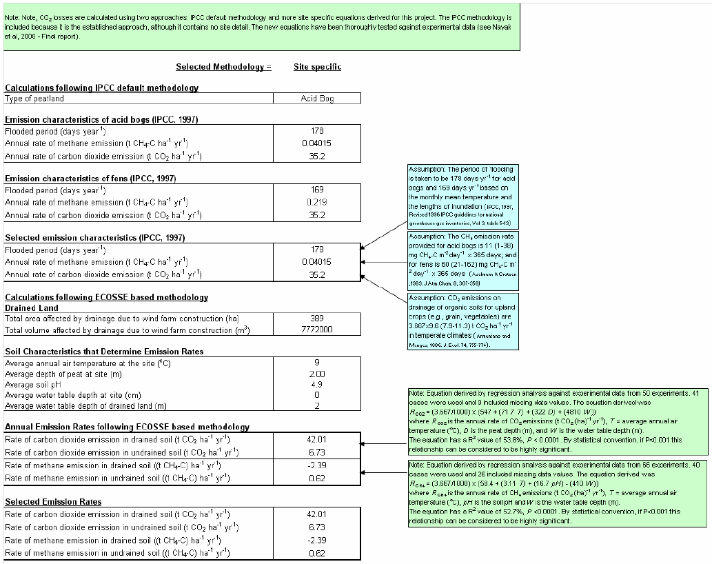
Figure 7.6.10. Emission rates from soils
7.6.11. Losses of dissolved and particulate organic carbon
Dissolved and particulate organic carbon losses are estimated with respect to the carbon dioxide emissions.
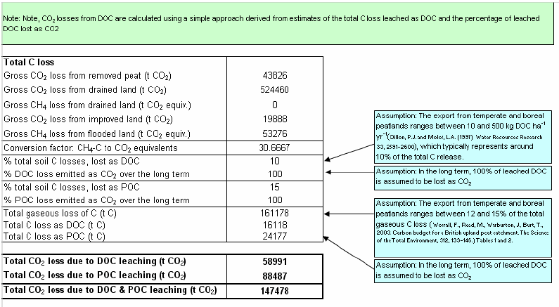
Figure 7.6.11. Carbon dioxide losses associated with leaching of dissolved and particulate organic carbon
7.6.12. Carbon dioxide loss due to forestry felling
Carbon dioxide losses due to forest felling should only be included if the forestry was scheduled to be replanted following felling.
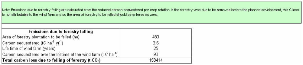
Figure 7.6.12. Carbon dioxide losses associated with felling of forestry
7.6.13. Carbon dioxide gains due to habitat improvement
Gains in soil carbon stocks due to habitat improvement of degraded bogs and land under felled forestry, restoration of peat in borrow pits, and early blocking of drains around hard-standing and foundations are calculated using the methodology selected in the input data worksheet.
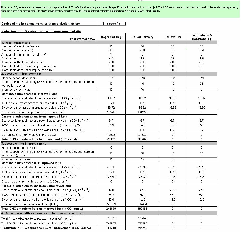
Figure 7.6.13. Carbon dioxide losses associated with felling of forestry
7.6.14. Example of how management practices and site selection can impact greenhouse gas emissions
The example given in the above sections represents a well-managed and carefully selected site. In the area of the felled forestry plantation (480 ha), it is planned that the habitat will be improved by blocking up drains and introducing bog species. Similarly, it is planned that the habitat of 385 ha of degraded bog will be improved. The site is schedule to be restored on decommissioning of the wind farm, again by blocking up drains and reintroducing bog plants. The 24.6 km of access tracks at the site have been constructed as floating roads, so attempting to reduce drainage of the site. The site is situated on level ground, so the extent of drainage around each drained feature is less than it would be if the site was highly sloped; at this site it is assumed less than 100 m. As a result, the greenhouse gas emissions from the soil and plants are estimated to be less than 7% of the CO 2 emission savings achieved taking fossil fuel sourced grid-mix as the counterfactual case. If, however, the good management practices are abandoned, the habitat is not longer improved, the site is not restored and the floating roads sink and require drainage, greenhouse gas emissions increase to 40% of the CO 2 emission savings. This increase is 20% due to loss of habitat improvement, 40% due to loss of site restoration, and 40% due to drainage of floating roads.
If the site selected was not level, and the extent of drainage around each drainage feature increased to 200 m, for the well-managed site the greenhouse gas emissions from the soil and plants increase to over 30% of the CO 2 emission savings achieved taking fossil fuel sourced grid-mix as the counterfactual case. If good management practices were not used, the emissions increase to over 100% of the emission savings; even without accounting for emissions associated with turbine manufacture and backup, there is a net C cost associated with the wind farm development on this poorly selected site. A higher proportion of the increase in emissions is attributable to not restoring the site on decommissioning than at the level site (57%). Therefore, it is particularly important to adequately restore a poorly selected site on decommissioning. Note that if the site is not decommissioned, but is recommissioned for a further period of operation, the loss of carbon due to not restoring the site is attributable to the recommissioned wind farm development, not to the original development.
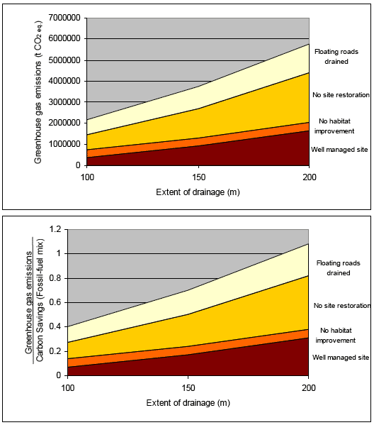
Figure 7.6.14. Changes in greenhouse gas emissions with management practices and selection of site
Contact
Email: Econsents@gov.scot