Scotland NCM software validation DSM and FI-SBEM software validation: guidance
Describes the methodology required for the validation of third party commercial Dynamic Simulation Modelling (DSM) and Front Interface Simplified Building Energy Modelling (FI-SBEM) software packages.
Appendix A: Test Cases
This Appendix provides the details of the Scotland software validation test cases. To stream-line the validation process for Scotland, the set of test cases used for England (under their 2021 NCM) will be adopted and tailored for use in Scotland. Software vendors will need to run test cases using their software under the Scotland Section 6 and EPC calculations. The details of the test cases are as described below.
There are two parts to the validation test cases:
- Part 1: Test cases 1 – 11 are for testing the software implementation of the Scotland Section 6 and EPC calculations.
- Part 2: Test cases 12 – 14 are for testing the software implementation of the Scotland Section 63 Action Plan
Part 1
Test cases 1 – 11 are based on the use of 5 buildings, 6 HVAC systems, 3 hot water systems and 2 LZC technologies. All of the buildings are setup to generally emulate the England Notional Building. Several specification details to highlight are:
The location should be set to Glasgow.
The building fabric properties (U-values, thermal mass, glazing g-value/light transmittance/frame factors, etc) should remain to match those described in the England NCM modelling guide (2021) for the Notional Building.
A.1 Test Cases for Software Validation
The vendor software will need to generate results for all the 11 test cases listed below.
| Test case |
Building type |
HVAC system type# |
HWS type# |
LZC type |
England test case no. |
|---|---|---|---|---|---|
| 1 |
Office## |
HVAC 1a |
HWS 1 |
1 |
|
| 2 |
Office## |
HVAC 2 |
HWS 2 |
2 |
|
| 3 |
Warehouse |
HVAC 6 |
HWS 2 |
6 |
|
| 4 |
Hotel### |
HVAC 2 |
HWS 3 |
9 |
|
| 5 |
Retail |
HVAC 2 |
HWS 2 |
10 |
|
| 6 |
School |
HVAC 1b |
HWS 1 |
13 |
|
| 7 |
Office## |
Ground floor HVAC 1a First floor: HAVC 2 |
HWS 2 |
18 |
|
| 8 |
Office## |
HVAC 8 |
HWS 1 |
19 |
|
| 9 |
School |
HVAC 9 |
HWS 2 |
New |
|
| 10 |
Warehouse |
HVAC 6 |
HWS 2 |
LZC 1 |
New |
| 11 |
Warehouse |
HVAC 6 |
HWS 2 |
LZC 2 |
New |
# The stated HVAC system and HWS apply to all spaces
## The toilet activity in the Office building will have additional local mechanical extract of 10 ac/hr
### The store room activity in the Hotel building will have no HVAC (i.e. only lighting)
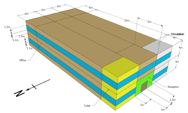
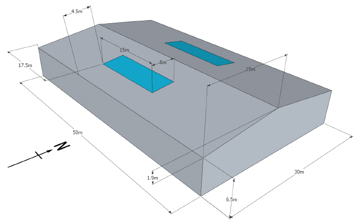
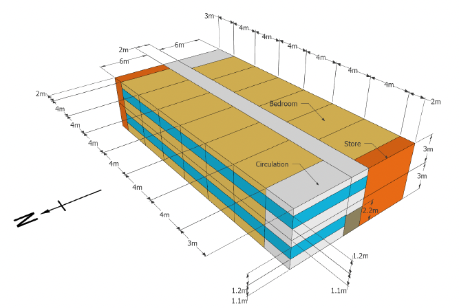
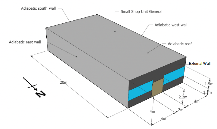
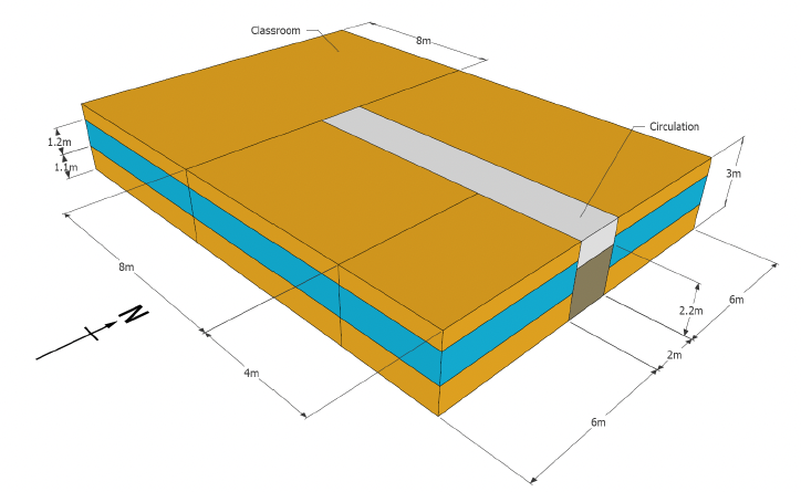
A.2 Building Geometry
The following table and figures describe the test cases building geometries.
| Geometry |
NCM Activity Building Type |
Dimensions |
|---|---|---|
| Office |
B1 Offices and workshop businesses |
Figure A.1 |
| Warehouse |
B8 Storage or distribution |
Figure A.2 |
| Hotel |
C1 Hotel |
Figure A.3 |
| Retail unit |
A1/A2 Retail and financial/professional services |
Figure A.4 |
| School |
D1 Non-residential institutions - Education |
Figure A.5 |
A.3 HVAC System Types
| HVAC type |
General description |
|---|---|
| HVAC 1a |
Natural ventilation with LTHW radiator heating
|
| HVAC 1b |
Natural ventilation with LTHW radiator heating
|
| HVAC 2 |
Fan coil system
|
| HVAC 6 |
Natural ventilation with multi-burner radiant heating
|
| HVAC 8 |
Fan coil system with district heating
|
| HVAC 9 |
Mechanical ventilation with heat recovery with electric heating only
|
A.4 Hot Water System Types
| HWS type |
General description |
|---|---|
| HWS 1 |
Fed from space heating system
|
| HWS 2 |
Electric resistance point-of-use
|
| HWS 3 |
Dedicated DHW heat pump
|
A.5 Low or Zero Carbon Systems
| Low or zero carbon systems |
General description |
|---|---|
| LZC 1 |
Photo-voltaic
|
| LZC 2 |
Wind generators
|
Part 2
Part 2 uses Test case 6 (school model) from Part 1 as the base model, with further modifications for the three Section 63 Action Plan test cases.
- Test case 12 – to test trigger of roof insulation and lighting control prescriptive measures whilst others are suppressed due to conditions not being met
- Test case 13 - to test trigger of roof insulation, draught proofing and lighting control prescriptive measures whilst others are suppressed due to conditions not met
- Test case 14
- to test trigger of draught proofing, heating control, boiler replacement and lamp replacement prescriptive measures
- to test set up of alternative measures and impact of not overriding corresponding prescriptive measures
| Item |
General description |
|---|---|
| Fabric (trigger) |
|
| Heating control (no trigger) |
|
| HVAC 1b (no trigger) |
|
| Lighting (no trigger) |
|
| Lighting control (trigger) |
|
| HWS 1 (no trigger) |
|
| Item |
General description |
|---|---|
| Fabric (trigger x 2) |
|
| Heating control (no trigger) |
|
| HVAC 1b (no trigger) |
|
| Lighting (no trigger) |
|
| Lighting control (trigger) |
|
| HWS 1 (no trigger) |
|
| Item |
General description |
|---|---|
| Fabric (trigger) |
|
| Heating control (trigger) |
|
| HVAC 1b (trigger) |
|
| Lighting (trigger) |
|
| Lighting control (no trigger) |
|
| HWS 1 (no trigger) |
|
| Item |
General description |
|---|---|
| Heating control |
|
| HVAC 1b |
|
| Lighting |
|
| HWS 1 |
|
| LZC |
|
Contact
Email: buildingstandards@gov.scot