3.10 Precipitation
|
Rain penetration shows up as damp patches, usually after heavy rain, on the inside of external walls, around door or window openings or on ceilings. It can be difficult to pinpoint the exact route the rainwater is taking. For example, a damp patch on a ceiling could be the result of a faulty flashing or damaged felt on a flat roof some distance away from the damp patch.
Similarly, unless they have adequate damp proof courses and flashings, materials in parapets and chimneys can collect rainwater and deliver it to other parts of the dwelling below roof level. Penetration occurs most often through walls exposed to the prevailing wet winds, usually south-westerly or southerly. There is evidence that the amount of rainfall has increased across much of Scotland. In addition, the majority of research indicates that this trend may continue as a consequence of climate change.
There are numerous publications providing good practice guidance on methods of preventing rain penetration to internal surfaces of buildings. BRE book ‘Roofs and Roofing – performance, diagnosis, maintenance, repair and the avoidance of defects’ provides helpful guidance for building professionals to address these problematic issues.
Explanation of terms - the following terms are included to provide clarity to their meaning in the guidance to this standard.
A vented cavity means a cavity with openings to the outside air placed so as to allow some limited, but not necessarily through air movement. The openings are normally located at low level where they can also act as weep holes to drain water from the cavity.
A ventilated cavity means a cavity with openings to the outside air placed so as to promote through movement of air. The openings should be located at high and low level.
Conversions - in the case of conversions, as specified in regulation 4, the building as converted shall meet the requirements of this standard in so far as is reasonably practicable, and in no case be worse than before the conversion regulation 12, schedule 6).
A floor, wall, roof or other building element exposed to precipitation, or wind driven moisture, should prevent penetration of moisture to the inner surface of any part of a dwelling so as to protect the occupants and to ensure that the building is not damaged.
For external wall constructions it is important that the wall is designed and constructed to suit the degree of exposure to wind and rain that it may be subject to.
BS EN ISO 15927-3: 2009 and BS 8104: 1992 provide a range of methodologies for the assessment of wind driven rain on the walls of a building:
BS EN ISO 15927-3: 2009 – This methodology, which is based closely on BS 8104, uses two procedures to analyse hourly wind and rain data, collected for any location over a minimum 10 year period, to calculate a driving rain index.
BS 8104: 1992 – This methodology determines the degree of exposure of a wall by using historical wind and rain data mapped at specific locations across the country.
An alternative simplified approach is provided within BR 262 ‘Thermal Insulation: Avoiding the risks’. This document is based on BS 8104 and provides a map that indicates exposures zones.
Some types of buildings, such as carports or storage of outdoor equipment, can be unaffected by damp penetration and the following guidance therefore may not be relevant.
When using any of the constructions below, the following general recommendations should be followed for walls or roofs, as appropriate:
masonry walls of bricks and/or blocks incorporating damp-proof courses, flashings and other materials and components constructed in accordance with the relevant recommendations of BS 5628: Part 3: 2005. The construction used should suit the degree of exposure to wind and rain as described in BS EN ISO 15927-3: 2009 or BS 8104: 1992
masonry walls incorporating external rendering which conforms to the relevant recommendations of BS 5262: 1991, to suit the degree of exposure and the type of masonry
masonry walls of natural stone or cast stone blocks constructed in accordance with the relevant recommendations of BS 5628: Part 3: 2005 and to suit the degree of exposure to wind and rain as described in BS EN ISO 15927-3: 2009 or BS 8104: 1992
masonry cavity walls incorporating insulation material, either as a complete or partial cavity fill, where the insulating material is the subject of a current certificate issued under the relevant conditions of an independent testing body. The walls should be constructed in accordance with the terms of the certificate and to suit the degree of exposure to wind and rain as described in BS EN ISO 15927-3: 2009 or BS 8104: 1992; and the relevant recommendations of the following British Standards:
Table 3.3. Cavity wall insulation
| Materials or conditions | British Standards |
|---|---|
| Urea formaldehyde (UF) foam | BS 5617: 1985 and BS 5618: 1985 |
| Man-made mineral fibre (slabs) | BS 6676: Part 1: 1986 |
| Assessment of walls for filling | BS 8208: Part 1: 1985 |
roofs with copper, lead, zinc and other sheet metal roof coverings require provision for expansion and contraction of the sheet material. In 'warm deck' roofs, in order to reduce the risk of condensation and corrosion, it may be necessary to provide a ventilated air space on the cold side of the insulation and a high performance vapour control layer between the insulation and the roof structure. It may also be helpful to consult the relevant trade association
walls or roofs incorporating cladding materials constructed in accordance with the recommendations of the following British Standards or Codes of Practice:
Table 3.4. Wall and roof cladding materials
| Materials and conditions | Element | British Standards and Codes of Practice |
|---|---|---|
| Aluminium | wall or roof | CP 143: Part 15: 1973 (1986) |
| Galv. corrugated steel | wall or roof | CP 143: Part 10: 1973 |
| Lead | wall or roof | BS 6915: 2001 |
| Copper | wall or roof | CP 143: Part 12: 1970 (1988) |
| Slates and tiles | wall or roof | BS 5534: Part 1: 2003 |
| Zinc | wall or roof | CP 143: Part 5: 1964 |
| Non-loadbearing walls | wall or steep roof | BS 8200: 1985 |
| PC concrete cladding | wall | BS 8297: 2000 |
| Natural stone cladding | wall | BS 8298: 1994 |
| Flat roofs | roof | BS 6229: 2003 |
| Bitumen felt | roof | BS 8217: 2005 |
| Mastic asphalt | roof | BS 8218: 1998 |
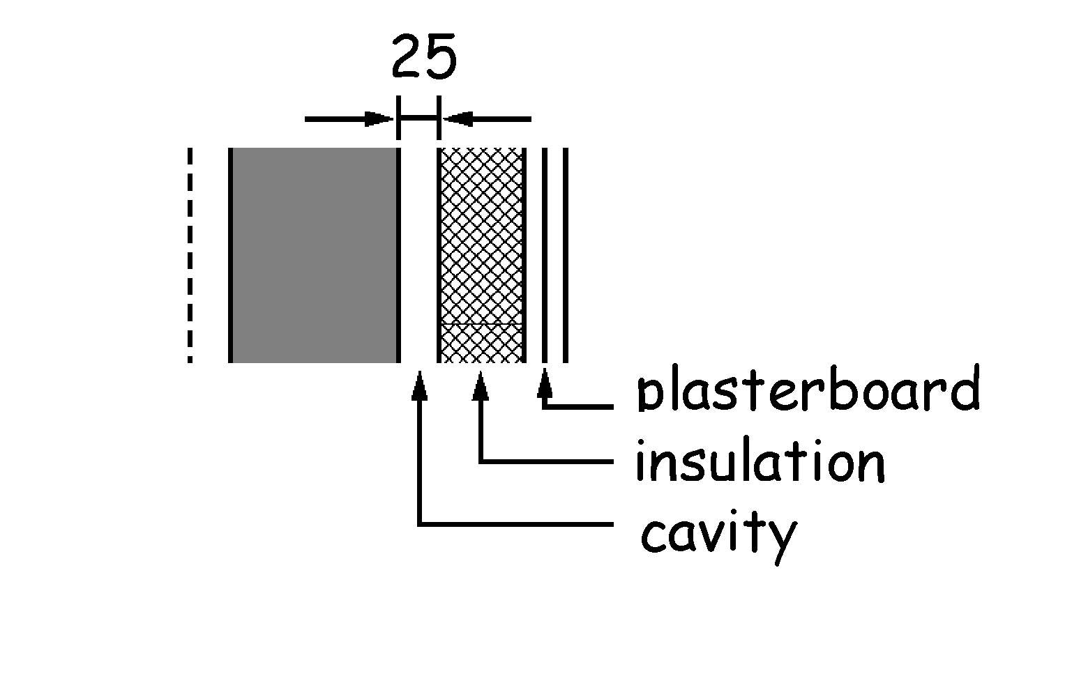
The following sketches provide guidance on recommended methods of construction to prevent rain penetration to the inner surfaces of the building. The thickness and other dimensions quoted are the minimum recommended unless otherwise stated. Greater figures are therefore possible.
| Wall type A (solid wall with internal insulation) Solid wall, 200mm thick of bricks, blocks or slabs of clay, calcium silicate, concrete or cast stone. Wall rendered or unrendered externally. Insulation and plasterboard internally, with a cavity 25mm wide. |
|
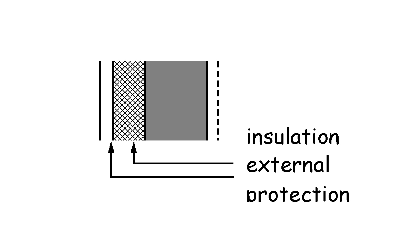
| Wall type B (solid wall with external insulation)- Solid wall as (A) above. Insulation applied to the external surface of the wall; protected externally either by cladding (of sheets, tiles or boarding) with permanent ventilation, or by rendering. Wall with or without an internal surface finish of plaster or plasterboard. |
|
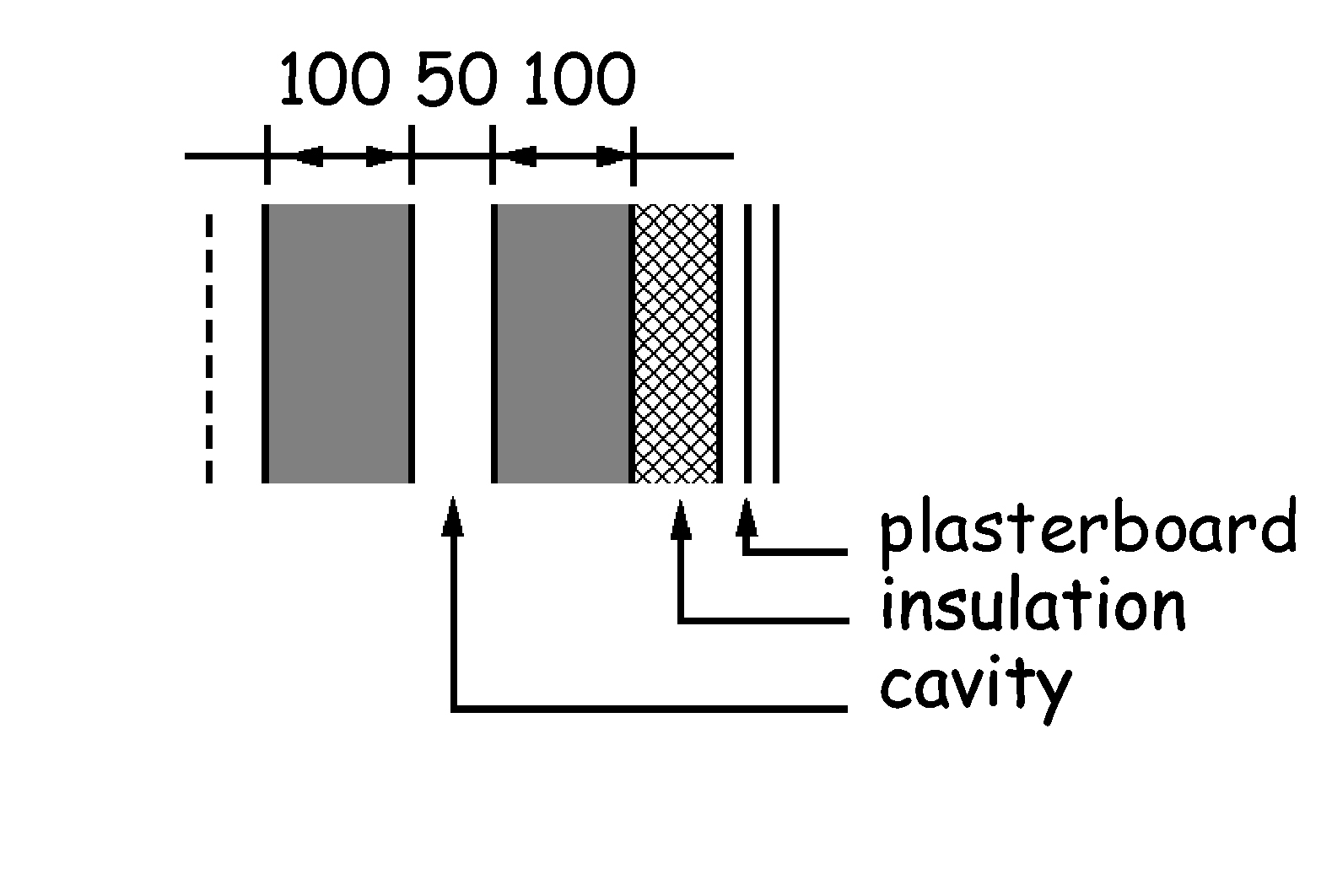
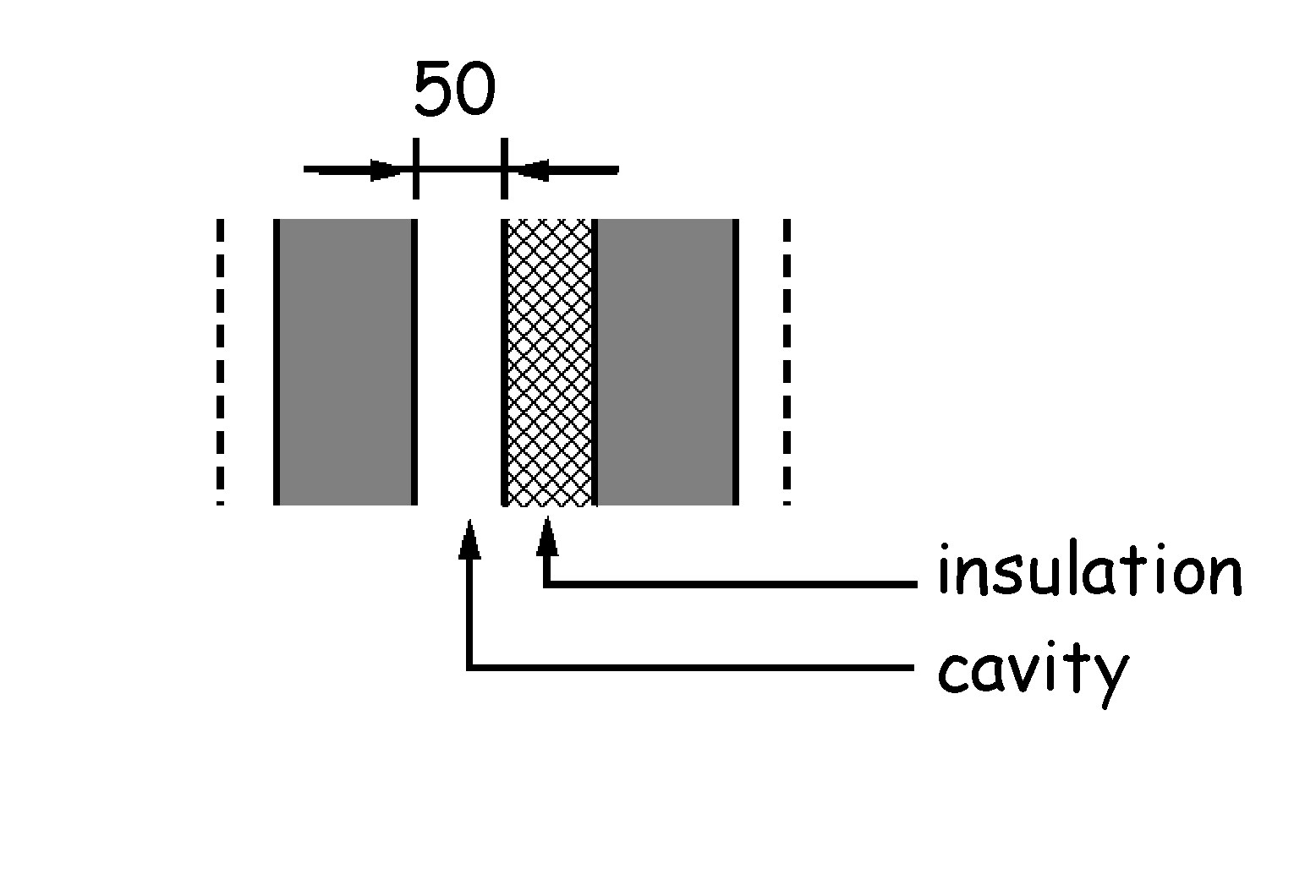
| Wall type A (cavity wall with internal insulation) - Cavity wall of 2 leaves of masonry separated by a 50mm cavity; each leaf, 100mm thick, of either bricks or blocks of clay, calcium silicate or concrete. Wall rendered or unrendered externally. Insulation applied as a lining to the internal surface of the wall and plasterboard. |
|
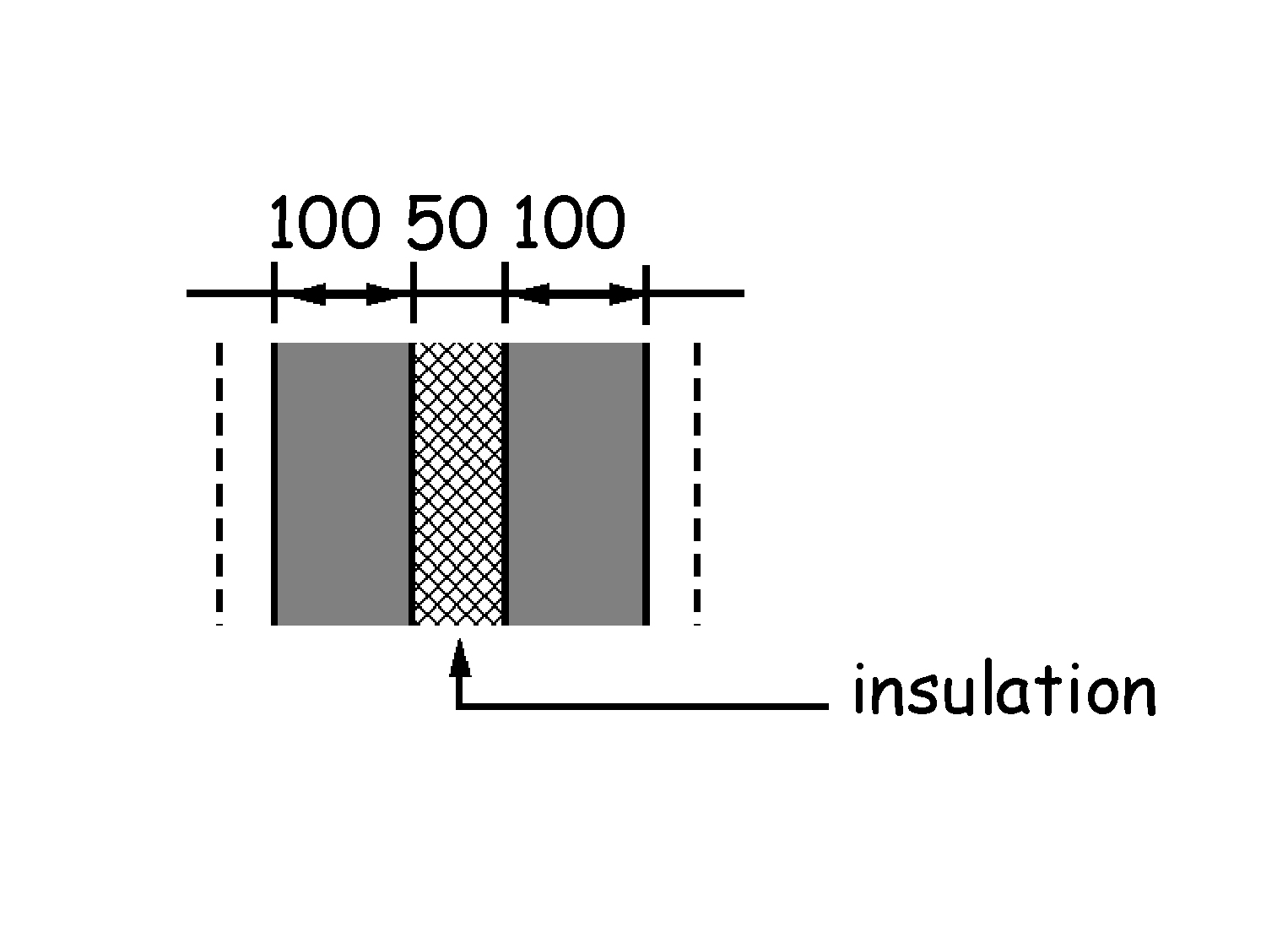
| Wall type B (cavity wall with cavity fill insulation) - Cavity wall as (A) above. Wall rendered or unrendered externally. Insulation applied as a cavity fill. Wall with or without an internal surface finish of plaster or plasterboard. This construction is only recommended for sheltered conditions. |
|
| Wall type C (cavity wall with partial fill insulation) - Cavity wall as (A) above. Wall rendered or unrendered externally. Insulation applied to either leaf as a partial cavity fill so as to preserve a residual space of 50mm wide. Wall with or without an internal surface finish of plaster or plasterboard. |
|
Careful consideration should be given to the detailing of an existing wall of a building when a conservatory or extension is added. The outer leaf of a previously external wall will become an internal wall and any moisture that enters the cavity could collect and cause serious damage to the building. Where the dwelling is located in an exposed location or where the existing construction might allow the passage of rain either through facing brick or a poorly rendered masonry wall, the use of a cavity tray along the line of the roof of the conservatory or extension may be appropriate. However in sheltered situations or where the detailing can prevent damage to the building as a result of rain penetration a raggled flashing (chased into the wall) may be sufficient.
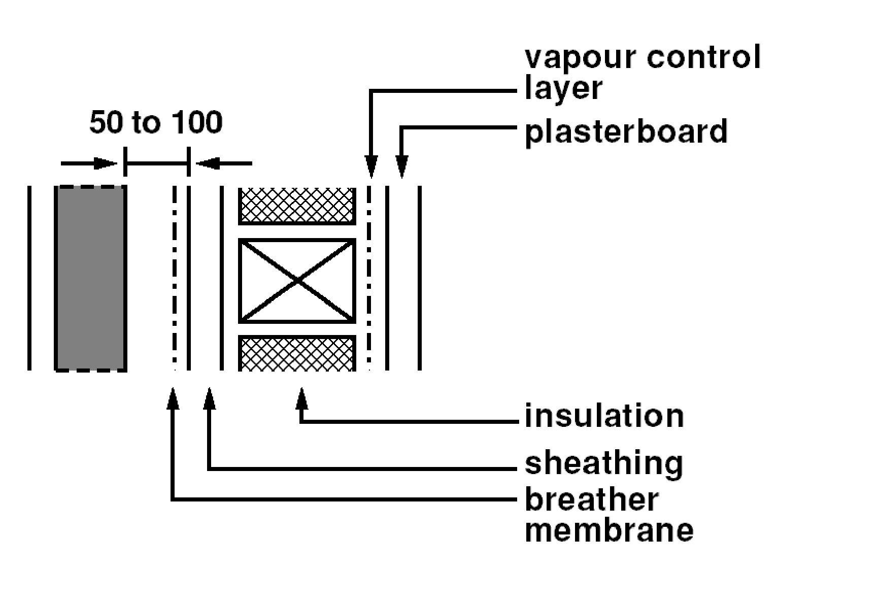
| Wall type A (masonry cladding) - Framed wall of timber studs and dwangs, with a vapour permeable sheathing to the framing covered with a breather membrane. Masonry external cladding of 100mm thick clay brick or block, concrete or calcium silicate brick or block, dense in-situ concrete, lightweight concrete or autoclaved aerated concrete, with an externally ventilated cavity in accordance with the guidance in clause 3.10.6. Masonry cladding rendered or unrendered externally. Insulation applied as an infill to the framing. The framing lined internally with a vapour control layer and plasterboard. |
|
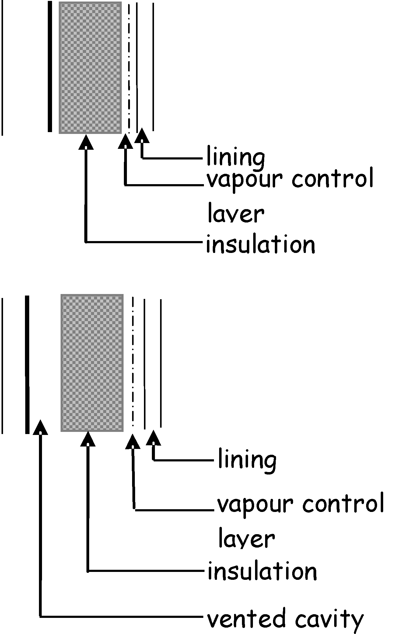
| Wall type B (weatherboarding, tile or slate cladding) - framed wall of timber studs and dwangs with a breather membrane. Cladding material, on battens and counter battens as required, of timber weather boarding, tile or slate. Insulation and internal lining as (A) above. |
|
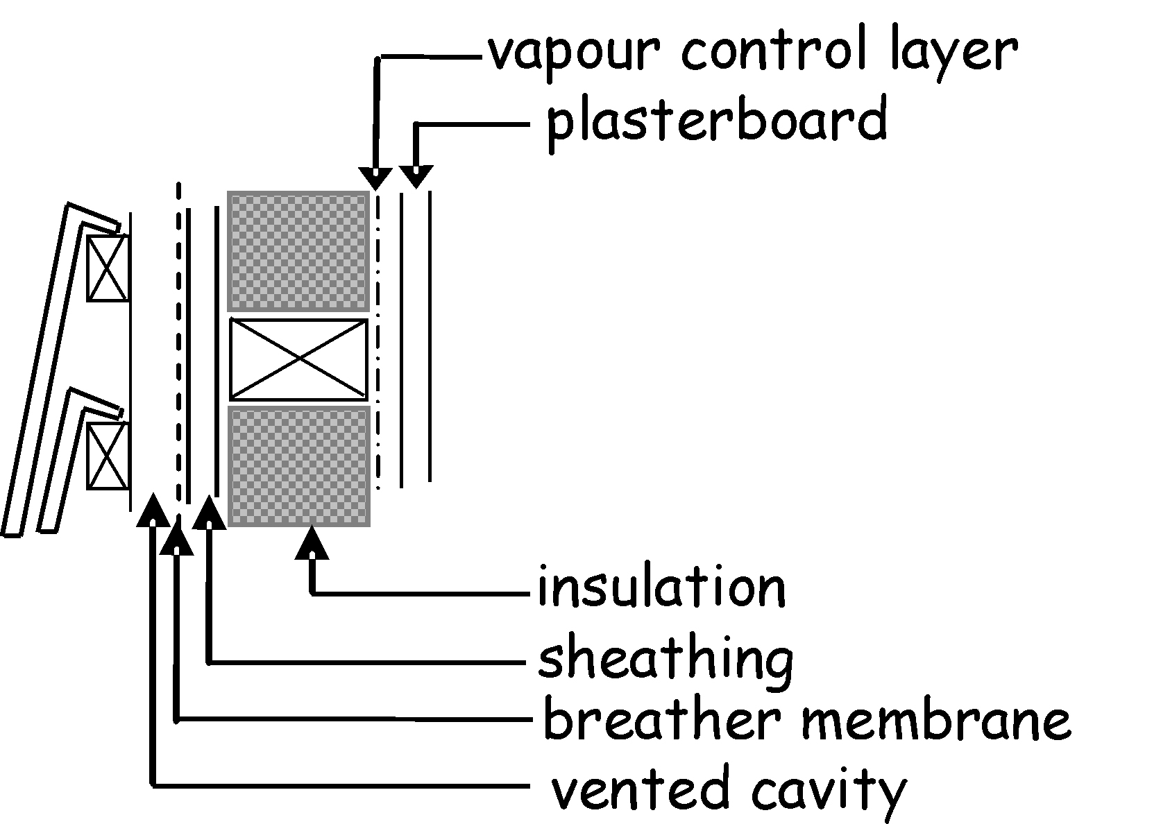
| Wall type C (sheet or panel cladding with/without ventilated cavity) - framed wall of timber or metal studs and dwangs. Sheet or panel cladding material of fibre cement, plastic, metal, GRP or GRC. Insulation applied either to the internal face of the framing with permanent ventilation behind any impervious cladding, or as an infill to the framing; in either case the wall lined internally with a vapour control layer and a lining. |
|
Ventilation of external wall cavities is necessary to prevent the build-up of excessive moisture that could damage the fabric of a building. Ventilation holes can also be used to drain excess water from the cavity that has entered through the outer leaf.
Timber frame - interstitial condensation is one of the major problems that need to be addressed in timber framed buildings. To reduce the amount of interstitial condensation to a level that will not harm the timber frame or sheathing, a cavity of at least 50mm wide should be provided between the sheathing and the cladding. Where timber, slate or tile cladding is used, the width of the cavity should be measured between the sheathing and the inner face of the cladding, ignoring the battens and counter battens.
Where the outer leaf is of timber, slate or tile clad construction, a vented cavity should be provided. A ventilated cavity should be provided for extra protection in severely exposed areas. Where necessary refer to BS 8104: 1992. Due to the air gaps inherent between the components of a timber, slate or tile clad wall, no proprietary ventilators should be necessary and a 10mm free air space should be sufficient.
Cavity barriers - where the wall cavity is sub-divided into sections by the use of cavity barriers e.g. at mid-floor level in a 2 storey house, the ventilators should be provided to the top and bottom of each section of the cavity. Care should be taken with rendered walls to prevent blockage of the ventilators.
Masonry outer leaf - where the outer leaf is of masonry construction, venting of the cavity is normally sufficient. Cavities should be vented to the outside air by installing ventilators with at least 300mm2 free opening area at 1.2m maximum centres. Precipitation can penetrate the outer leaf of an external wall and cavities are normally drained through weep holes. These weep holes can also provide the necessary venting.
The following sketches provide guidance on recommended methods of construction to prevent rain penetration to the inner surfaces of a building.
There is evidence to suggest that condensation in cold deck flat roofs can cause problems and these type of roofs should be avoided. Both the warm deck and warm deck inverted roof constructions, where the insulation is placed above the roof deck, are considered preferable. Further guidance is given to Standard 3.15, Condensation.
The following British Standards give recommendations on the design and construction of flat roofs:
BS 6229: 2003 – CoP for flat roofs with continuously supported coverings
BS 6915: 2001 – CoP Design and construction of fully supported lead sheet roof and wall cladding
BS 8217: 2005 – CoP for reinforced bitumen membranes
BS 8218: 1998 – CoP for mastic asphalt roofing CP 143-12: 1970 – CoP for sheet and wall coverings
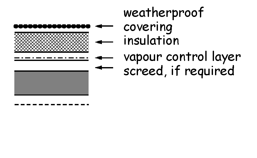
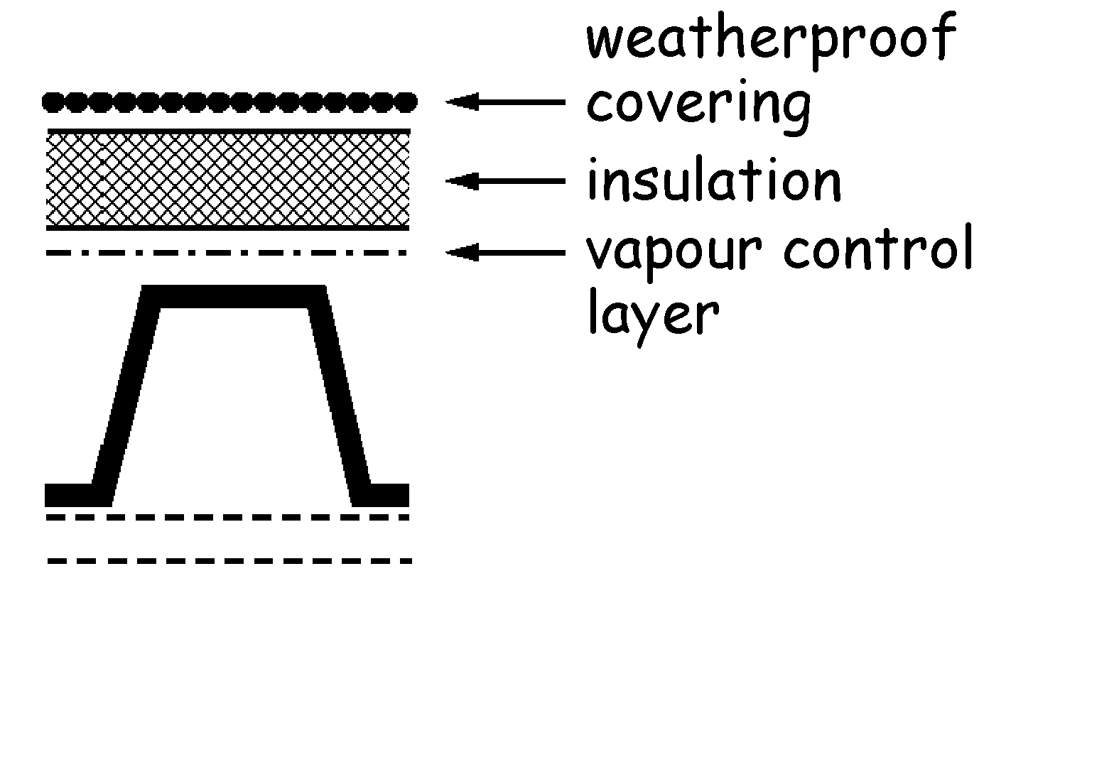
| Roof type A (concrete - warm roof) - flat roof structure of in-situ or precast concrete with or without a screed; with or without a ceiling or soffit. External weatherproof covering; with insulation laid on a vapour control layer between the roof structure and the weatherproof covering. [Note 1] |
|
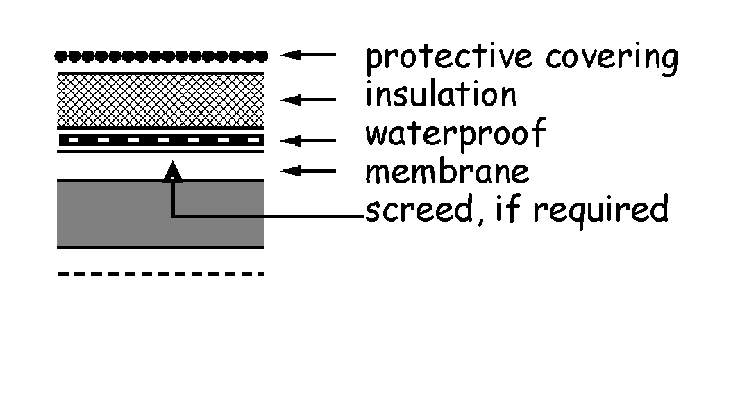
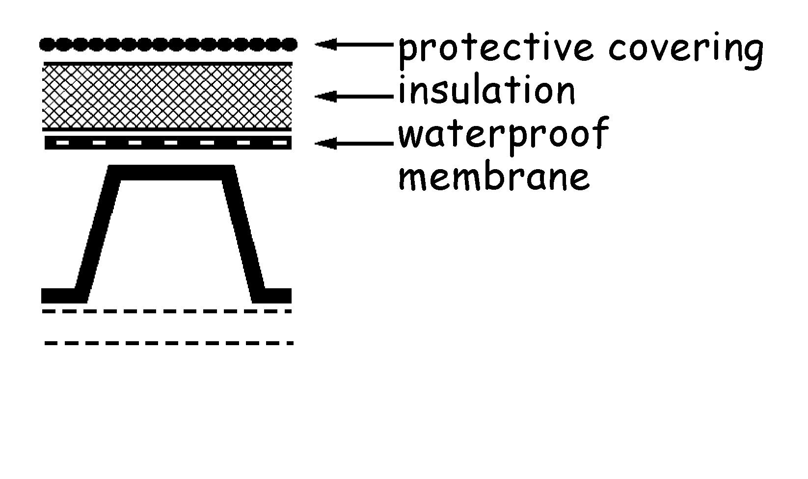
| Roof type B (concrete - inverted roof) - flat roof structure as (A) above. External protective covering; with low permeability insulation laid on a waterproof membrane between the roof structure and the external covering. |
|
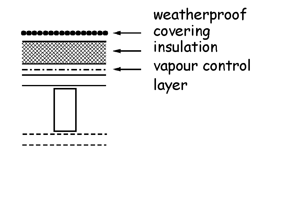
| Roof type C (timber or metal frame - warm roof) - flat roof structure of timber or metal-framed construction with a board decking 19mm thick; with or without a ceiling or soffit. External weatherproof covering, insulation and vapour control layer as (A) above. [Note 1] |
|
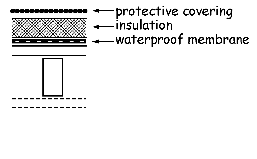
| Roof type D (timber or metal frame - inverted roof) - flat roof structure as (C) above. External protective covering, insulation and waterproof membrane as (B) above. |
|
| Roof type E (troughed metal decking - warm roof) - flat roof structure of timber or metal framed construction with a troughed metal decking; with or without a ceiling or soffit. External weatherproof covering and insulation and vapour control layer as (A) above. [Note 1] |
|
| Roof type F (troughed metal decking - inverted roof) - flat roof structure as (E) above. External protective covering, insulation and waterproof membrane as (B) above. |
|
| Note | |
|---|---|
Roof types A, C and E are not suitable for sheet metal coverings that require joints to allow for thermal movement. See also sub-clause f of clause 3.10.1. |
BS 5534: 2003 gives recommendations on the design, materials, installation and performance of slates, tiles and shingles including, amongst others, information on rain and wind resistance. The British Standard also provides a comprehensive list of other British Standards covering other less common pitched roof coverings.
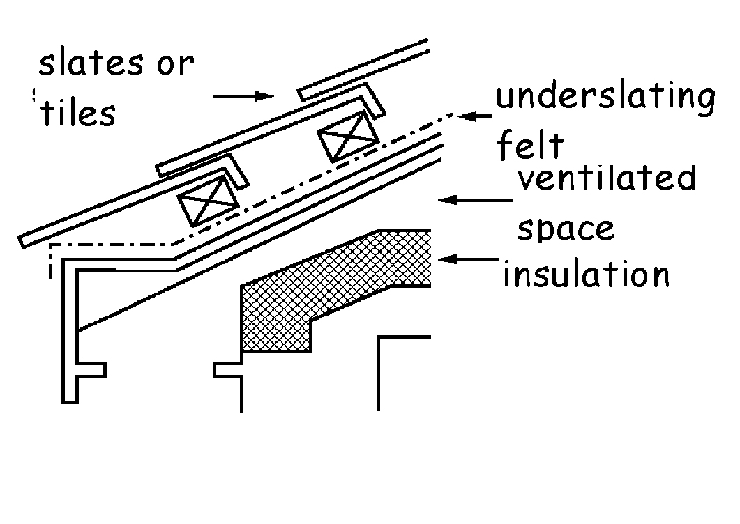
Roof type A (slate or tiles - insulation on a level ceiling) - pitched roof structure of timber or metal framed construction. External weatherproof covering of slates or tiles on under slating felt with or without boards or battens.
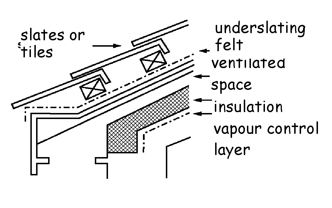
Roof type B (slate or tiles - insulation on a sloping ceiling) - pitched roof structure as (A) above. External weatherproof covering as (A).
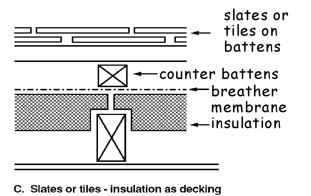
Roof type C (slate or tiles - insulation on decking) - pitched roof structure as (A) above with a decking of low permeability insulation fitted to and between the roof framing. External weatherproof covering of slates or tiles, with tiling battens and counter battens (located over roof framing), and a breather membrane laid on the insulation decking; with a sloping ceiling.
Roof type D (metal or fibre cement sheet - sandwich insulation) - pitched roof structure as (A) above. External weatherproof covering of metal or fibre cement sheet sandwich construction laid on purlins; with insulation sandwiched between the external and soffit sheeting; and with or without a ceiling. [Note 2]
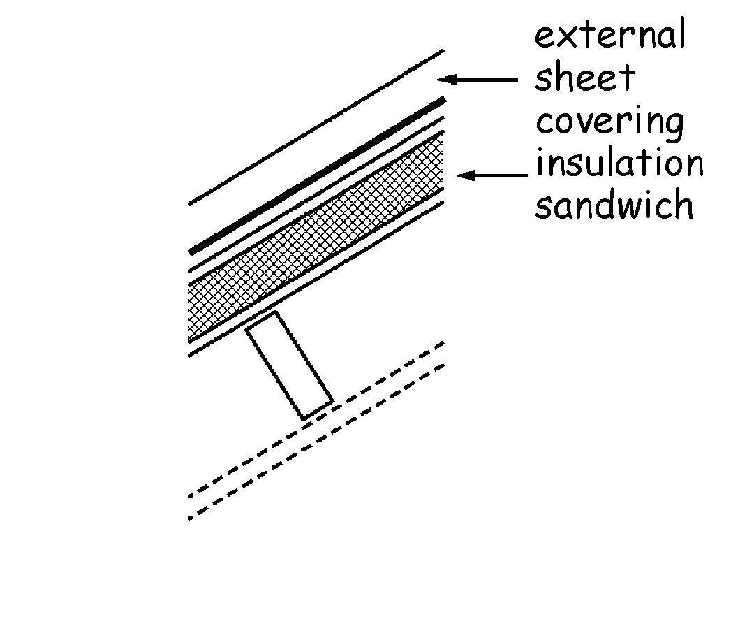
Note Roof type (D) is not suitable for sheet metal coverings that require joints to allow for thermal movement. See also sub-clause f of clause 3.10.1.