3.9 Private wastewater treatment systems – infiltration systems
|
The intention of this standard is to ensure that non-mains drainage systems are designed and constructed to a standard so that the discharges from them do not contribute to environmental pollution and will achieve statutory environmental standards. Subject to discharge authorisation from SEPA, (see clause 3.8.5) wastewater from treatment systems can either discharge to land via an infiltration system or to watercourses, lochs or coastal waters. The guidance to this standard deals with discharges to land via infiltration systems. The infiltration method will form a critical part of the treatment system and care must be taken in the type, design and location chosen to avoid environmental pollution. The guidance to this standard should be used in conjunction with the guidance to Standard 3.8 when designing wastewater treatment systems.
Several hundreds of wastewater treatment systems are thought to cause pollution problems every year. These problems occur mainly because of poor location, poor drainage field design or lack of maintenance.
Conversions - in the case of conversions, as specified in regulation 4, the building as converted shall meet the requirements of this standard (regulation 12, schedule 6).
An infiltration system serving a private wastewater treatment plant, septic tank or for greywater should be constructed in ground suitable for the treatment and dispersion of the wastewater discharged. This can be achieved by following the guidance below.
A ground assessment and soil percolation test should be carried out to determine the suitability of the ground. The following three step procedure should be followed:
First, carry out a preliminary ground assessment. The following check list indicates the actions that should be taken and the type of information that should be collected:
consult SEPA, verifier and the Environmental Health Officer as required
consult SEPAs latest groundwater protection policy
identification of the underlying geology and aquifers
whether the ground is liable to flooding
nature of the sub-soil and groundwater vulnerability
implication of plot size
proximity of underground services
ground topography and local drainage patterns
whether water is abstracted for drinking, used in food processing or farm dairies
implication for, and of, trees and other vegetation
location of surface waters and terrestrial ecosystems.
The preliminary assessment may indicate that the ground is unsuitable for the installation of an infiltration system, in which case an alternative disposal method should be considered.
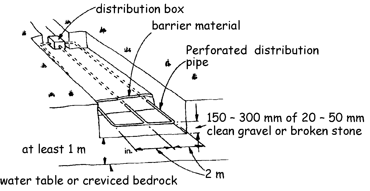
Second, a trial hole should be dug to determine the position of the water table and soil conditions. This trial hole will enable the sub-soil type to be determined. The trial hole should be a minimum of 2m deep, or a minimum of 1.5m below the invert of the proposed distribution pipes. The trial hole should be left covered for a period of 48 hours before measuring any water table level. Subsoils that overlay bedrock allow water to move through the pore spaces between the grains of material of which they are composed. They are the first line of defence against pollution and act as a protecting filtering layer. Where these materials are unsaturated, pollution attenuation processes are often enhanced. Water flows through much of Scotland’s bedrock via fissures. Attenuation of contaminants is limited in these cases. For safe and effective dispersal of the wastewater, the groundwater and bedrock should be at least 1m below the bottom of the distribution pipes. It should also be noted that it is the seasonally highest level of the water table that should be determined for the infiltration area.
Third, to determine the type of infiltration system and the area of ground required, percolation tests should be carried out. These percolation tests should be carried out using either of the following methods:
expert examination of the soil distribution analysis, using the method described in BS 1377: Part 2: 1990, or
expert in-situ testing using either the Constant Head or Tube Permeameter as described in CEN/TR 12566–2–2005, or
excavate a minimum of two percolation holes, not less than 5m apart along the line of and below the proposed invert level of the effluent distribution pipe. Each hole should be 300mm square to a depth of 300mm. Where deep drains are necessary, the holes should conform to this shape at the bottom but may be enlarged above the 300mm level to facilitate safe excavation. Fill the 300mm square section of the holes to a depth of at least 300mm with water and allow them to seep away overnight. It is important to saturate the soil surrounding the test holes to simulate day to day conditions in an operational drainage field. Next day, refill the test sections of the percolation holes with water to a depth of at least 300mm and observe the time (t) in seconds, for the water to seep away from 75% to 25% full level. Divide this time by 150mm. The answer gives the average time in seconds (Vp) required for the water to drop 1mm. Take care when making the tests to avoid unusual weather conditions such as heavy rain, severe frost or drought. To obtain consistent results carry out the test at least 3 times for each percolation hole and take the average figure.
The floor area of a sub-surface drainage trench required to disperse effluent from treatment plants or septic tanks may be calculated from the following formula:
A= P x Vp x 0.25
A - is the area of the sub-surface drainage trench, in m2
p - is the number of persons served by the tank and
Vp - is the percolation value obtained, as described above, in secs/mm.
For wastewater that has received the benefit of secondary treatment followed by settlement, this area may be reduced by 20%, i.e.
A = P x Vp x 0.2
An infiltration system serving a private wastewater treatment plant or septic tank should be designed and constructed to suit the conditions as determined by the ground into which the treated wastewater is discharged. An infiltration system should be designed and constructed in accordance with the following guidance:
Fast percolation rates - where the percolation value (as demonstrated by the percolation test) is not more than 15 secs/mm, in accordance with the requirements of SEPA
Normal percolation rates - where the percolation value (as demonstrated by the percolation test) is more than 15 secs/mm and not more than 100 secs/mm, as:
a piped infiltration trench system in accordance with national annex NA of BS EN 752: 2008, using perforated, rigid pipes with a smooth internal surface, or
a piped infiltration bed system in accordance with the diagram below, or
any system described under ‘slow and very slow percolation rates’.
Where the percolation value (as demonstrated by the percolation test) is more than 100 secs/mm and not more than 140 secs/mm, as:
a reed bed complying with the requirements of the BRE, Good Building Guide, GBG 42, Parts 1 and 2 together with a piped infiltration system described in sub-clauses (a) and (b) with a normal percolation rate, or a suitable outfall, or
a constructed wetland, other than a reed bed, to a professionally prepared design and constructed by specialist contractor(s), or
a proprietary filtration system designed, constructed and installed in accordance with the conditions of a notified body, or
any other equivalent filtration system designed by a specialist in this subject and constructed by specialist contractor(s).
Very slow percolation rates - where the percolation value (as demonstrated by the percolation test) is more than 140 secs/mm:
as a system described under ‘slow percolation rate’ that does not use an infiltration system for the final treated wastewater, or
for domestic sized buildings, by designing and constructing a mound filter system in accordance with BR 478, Mound Filter Systems for the treatment of domestic wastewater'.
The disposal of greywater (from baths, showers, washbasins, sinks and washing machines) may be accomplished by an infiltration field the area of which can be calculated from the following:
A= P x Vp x 0.2
A - is the area of the sub-surface drainage trench, in m2
p - is the number of persons served, and
Vp - is the percolation value obtained, as described above, in secs/mm.
An infiltration system serving a private wastewater treatment plant or septic tank should be located to minimise the risk of pollution. An infiltration field should be located in accordance with the following guidance:
at least 50m from any spring, well or borehole used as a drinking water supply, and
at least 10m horizontally from any watercourse (including any inland or coastal waters), permeable drain, road or railway.
Research has shown that there are no health issues that dictate a safe location of an infiltration field relative to a building. However damage to the foundations of a building is likely to occur where discharge is too close to the building. It is sensible to ensure that any water bearing strata directs any effluent away from the building.
To prevent any such damage therefore, every part of an infiltration system serving a private wastewater treatment plant or septic tank should be located at least 5m from a building. An infiltration system should also be located at least 5m from a boundary in order that an adjoining plot is not inhibited from its full development potential.
However the ground strata or permeability of the soil may influence this dimension and it may be reduced slightly where the strata directs any groundwater away from the foundations or if the soil is free draining. Indeed, to preserve the structural integrity of the building, it may be prudent to increase the dimension where ground conditions would allow wastewater to collect around the building's foundations.