3.19 Combustion appliances – relationship to combustible materials
|
Combustion appliances and their component parts, particularly solid fuel appliance installations, generate or dissipate considerable temperatures. Certain precautions need to be taken to ensure that any high temperatures are not sufficient to cause a risk to people and the building. The characteristics of solid fuel and some older style oil-firing appliances are more onerous than modern oil and gas-fired appliances.
Conversions - in the case of conversions, as specified in regulation 4, the building as converted shall meet the requirements of this standard in so far as is reasonably practicable, and in no case be worse than before the conversion (regulation 12, schedule 6).
Combustible material should not be located where the heat dissipating through the walls of fireplaces or flues could ignite it. All combustible materials therefore should be located at least 200mm from the surface surrounding a flue in a masonry chimney. However some combustible materials will not be a risk and do not need a 200mm separation distance nor do the flue gasses generated from some appliances reach a sufficiently high temperature to require it. The following materials may be located closer than 200mm to the surface surrounding a flue in a chimney:
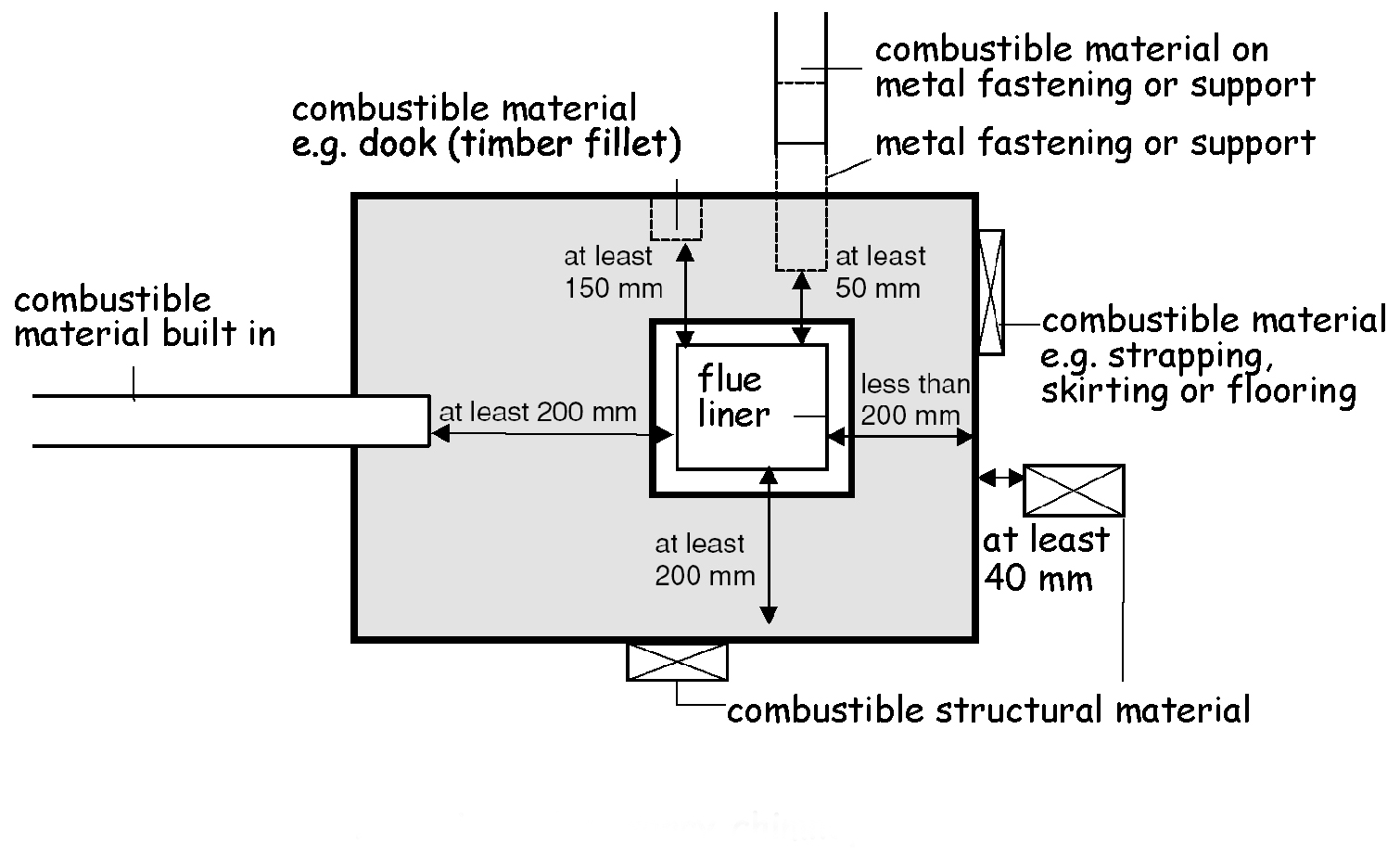
Any metal fastening in contact with combustible material, such as a joist hanger, should be at least 50mm from the surface surrounding a flue to avoid the possibility of the combustible material catching fire due to conduction.
BS EN 1806: 2006 relates to clay flue-block chimneys but does not give a value for distances to combustible materials. These types of chimneys therefore should be regarded as custom built chimneys and the minimum values in this clause 3.19.1 or clause 3.19.2 should be used and declared.
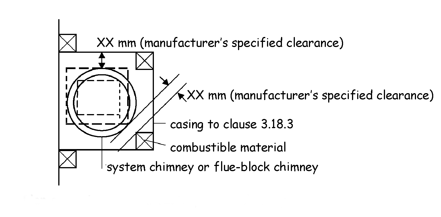
System chimneys do not necessarily require to be located at such a distance from combustible material. It is the responsibility of the chimney manufacturer to declare a distance ‘XX’, as stipulated in BS EN 1856-1: 2003 and BS EN 1858: 2003 as being a safe distance from the chimney to combustible material. At this distance, the temperature of adjacent combustible materials during operation of the appliance at its rated output should not exceed 85ºC when related to an ambient temperature of 20ºC.
BS EN 1806: 2006 relates to clay flue-block chimneys but does not give a value for distances to combustible materials. These types of chimney therefore should be regarded as a custom built chimney and the minimum values in this clause 3.19.1 or clause 3.19.2 should be used and declared.
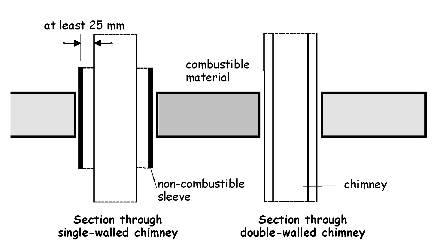
There should be a separation distance where a metal chimney passes through combustible material. This is specified, as part of the designation string for a System chimneys when used for oil or gas, as (Gxx), where xx is the distance in mm. Where no data is available, the separation distance for oil or gas applications with a flue gas temperature limit of T250 or less should be 25mm from the outer surface of a single-walled chimney to combustible material. The 25mm should be measured from the surface of the inner wall of a double-walled chimney. There is no need for a separation distance if the flue gases are not likely to exceed 100ºC.
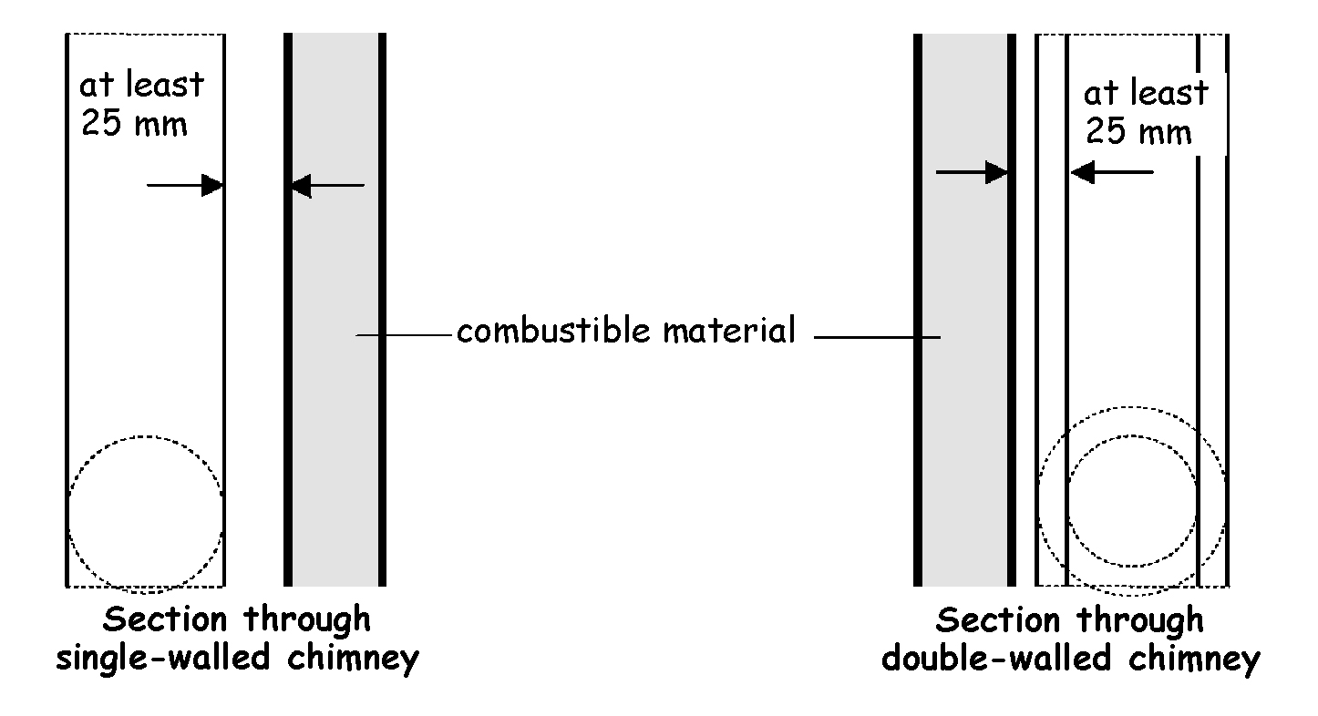
There should also be a separation distance where the metal chimney runs in close proximity to combustible material. The separation distance should be 25mm from the outer surface of a single-walled chimney to combustible material. The 25mm should be measured from the surface of the inner wall of a double-walled chimney. There is no need for a separation distance if the flue gases are not likely to exceed 100ºC.
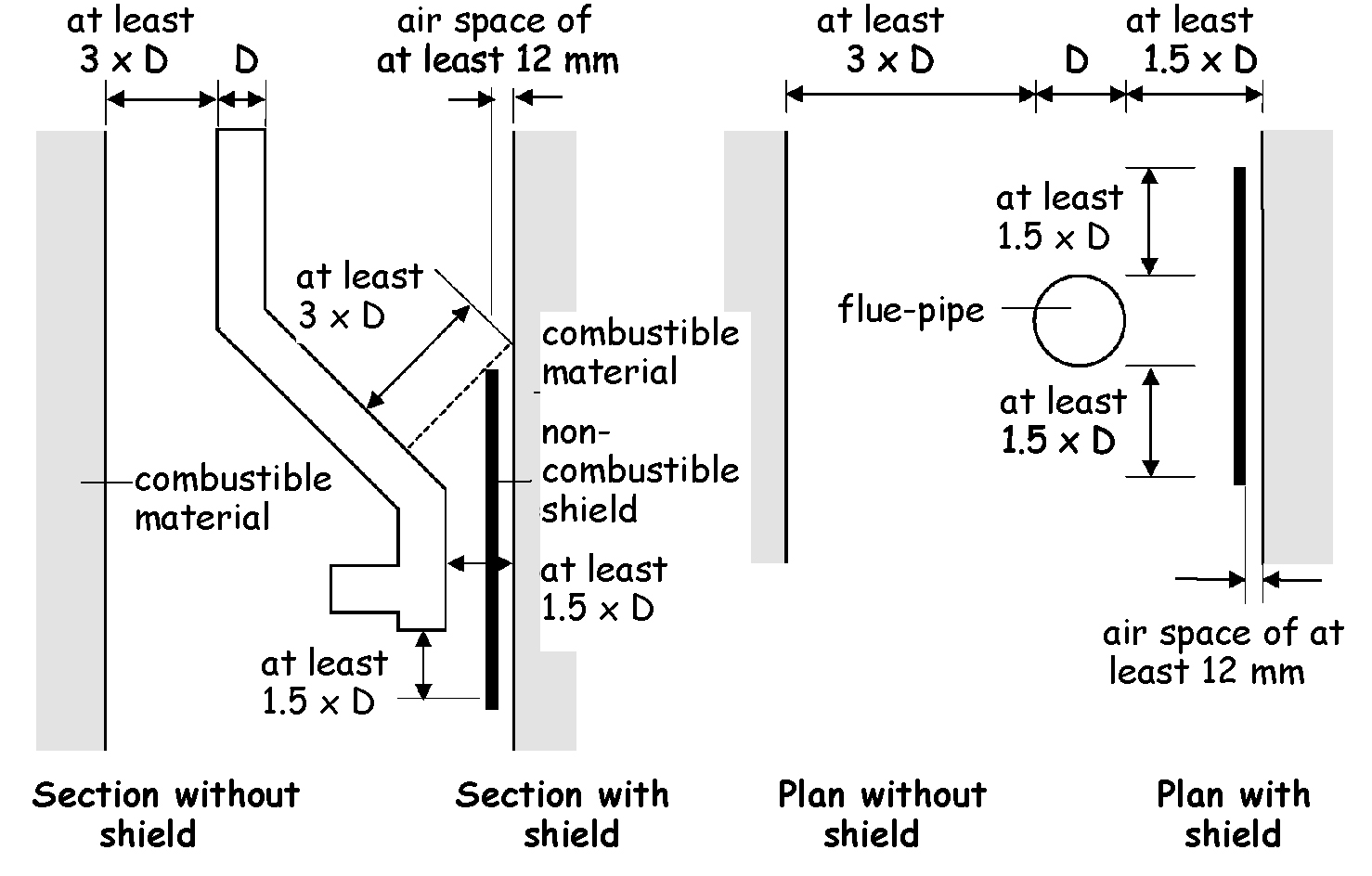
To prevent the possibility of radiated heat starting a fire, a flue-pipe should be separated from combustible material by:
a distance according to the designation of the flue-pipe in accordance with BS EN 1856-2: 2005, or
a distance equivalent to at least 3 times the diameter of the flue-pipe. However this distance may be reduced:
to 1.5 times the diameter of the flue-pipe, if there is a non-combustible shield provided in accordance with the following sketch or
to 0.75 times the diameter of the flue-pipe, if the flue-pipe is totally enclosed in non-combustible material at least 12mm thick with a thermal conductivity of not more than 0.065W/mK.
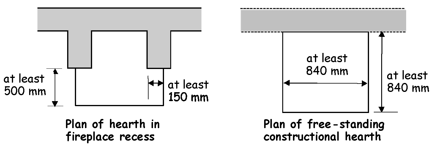
A solid fuel appliance should be provided with a solid,non-combustible hearth that will prevent the heat of the appliance from igniting combustible materials. A hearth should be provided to the following dimensions:
a constructional hearth at least 125mm thick and with plan dimensions in accordance with the following sketches or
a free-standing, solid, non-combustible hearth at least 840 x 840mm minimum plan area and at least 12mm thick, provided the appliance will not cause the temperature of the top surface of the hearth on which it stands to be more than 100ºC.
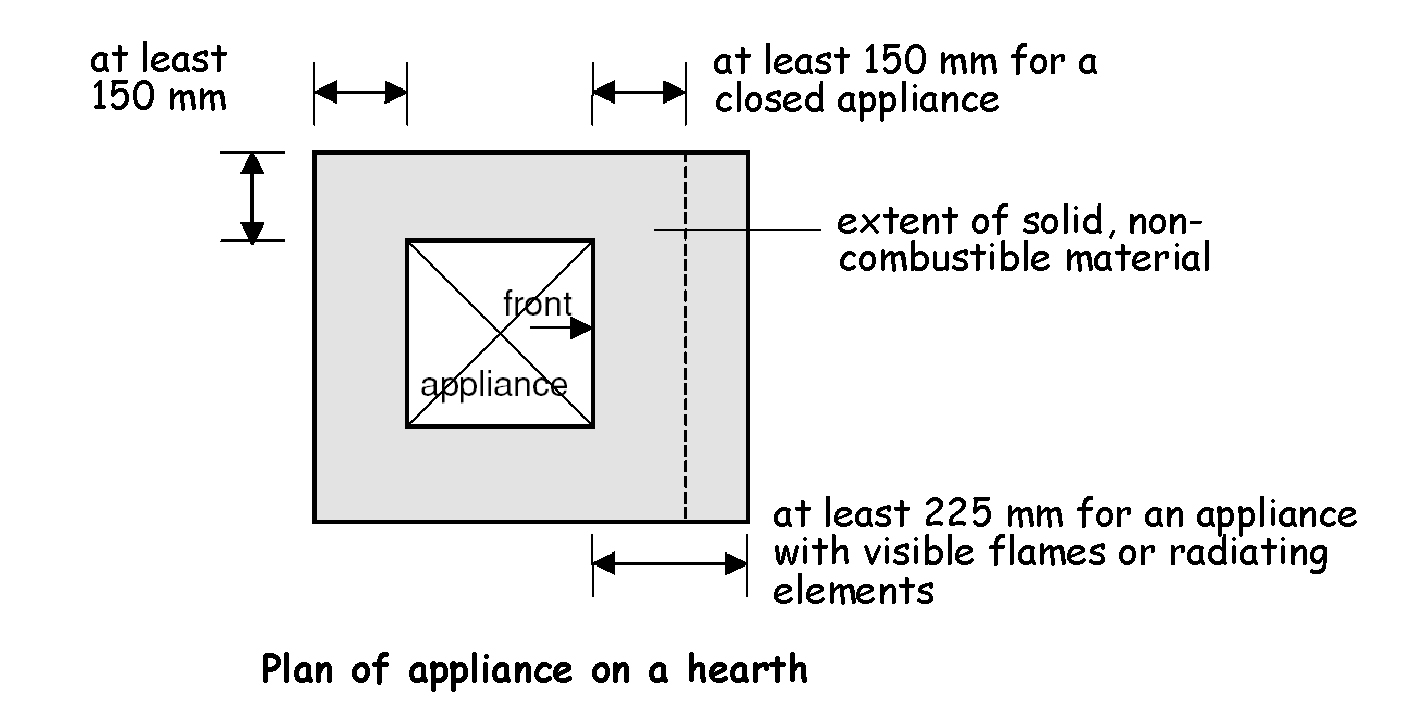
Not only should a solid fuel appliance sit on a hearth, but the appliance itself should also be located on the hearth such that protection will be offered from the risk of ignition of the floor by direct radiation, conduction or falling embers. The solid fuel appliance should be located on a hearth in accordance with the following diagram:
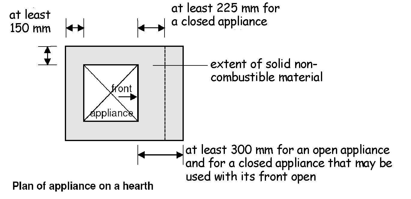
The 150mm does not apply where the appliance is located in a fireplace recess, nor does it apply where the back or sides of the hearth either abut or are carried into a solid, non-combustible wall complying with clause 3.19.8.
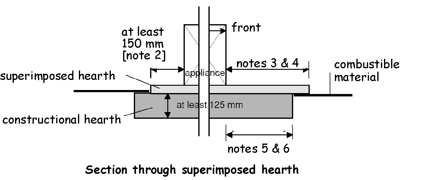
A solid fuel appliance may sit on a superimposed hearth provided the hearth is positioned partly or wholly on a constructional hearth. The superimposed hearth should be of solid, non-combustible material, usually decorative, and be at least 50mm thick in accordance with the following diagram:
Additional information:
SUPERIMPOSED HEARTH means a finish of solid, non-combustible material, usually decorative, at least 50mm thick and positioned on a constructional hearth.
There need not be a 150mm separation where the appliance is located in a fireplace recess, nor where the back or sides of the hearth either abut or are carried into a solid, non-combustible wall complying with clause 3.14.8.
At least 225mm for a closed appliance.
At least 300mm for an open appliance and for a closed appliance that may properly be used with its front open.
No part of the appliance should project over any edge of the constructional hearth.
At least 150mm to combustible material measured horizontally.
A hearth is not required beneath an oil-firing appliance if it incorporates a full sized, rigid non-combustible base and does not raise the temperature of the floor beneath it to more than 100ºC under normal working conditions. The base may be provided separately from the appliance. In other cases the appliance should stand on a hearth constructed and installed in accordance with the guidance for a solid fuel appliance.
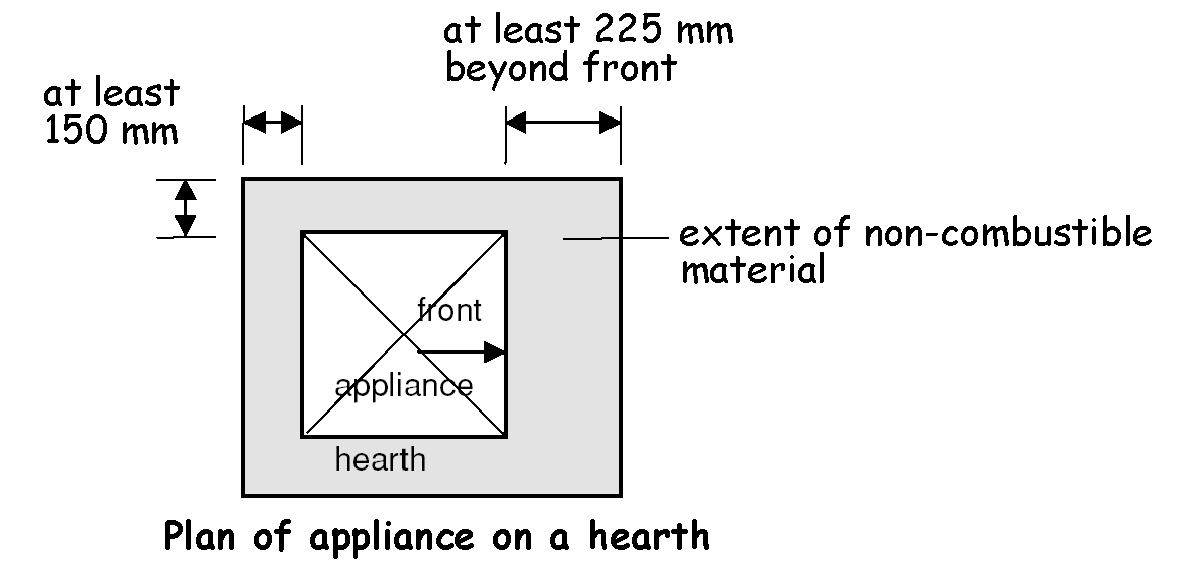
A floor-standing, oil-firing appliance should be positioned on the hearth in such away as to minimise the risk of ignition of any part of the floor by direct radiation or conduction. An oil-firing appliance should be located on a hearth in accordance with the following diagram:
The 150mm does not apply where the appliance is located in a fireplace recess, nor does it apply where the back or sides of the hearth either abut or are carried into a solid, non-combustible wall complying with clause 3.19.8.
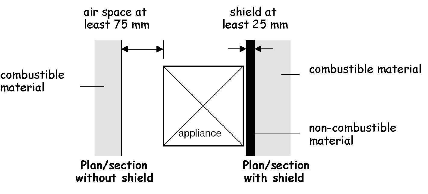
An oil-firing appliance should be separated from any combustible material if the temperature of the back, sides or top of the appliance is more than 100ºC under normal working conditions. Separation may be by:
a shield of non-combustible material at least 25mm thick, or
an air space of at least 75mm.
OFTEC Standard OFS A100 for boilers, OFS A101 for cookers and OFS A102 for room heaters defines suitable tests for measuring the temperature of the back, sides and top of an oil-firing appliance.
A gas-fired appliance should be provided with a hearth in accordance with the following recommendations:
Clause 12 of BS 5871-1: 2005 for a gas fire, convector heater and fire/back boiler
Clause 12 of BS 5871-2: 2005 for an inset live fuel-effect gas appliance
Clause 11 of BS 5871-3: 2005 for a Decorative fuel-effect gas appliance
for any other gas-fired appliance, by a solid, heat resistant, non-combustible, non-friable material at least 12mm thick and at least the plan dimension shown in the diagram to this specification:
The 150mm does not apply where the appliance is located in a fireplace recess, nor does it apply where the back or sides of the hearth either abut or are carried into a solid, non-combustible wall complying with clause 3.19.8.
However a hearth need not be provided:
where every part of any flame or incandescent material in the appliance is at least 225mm above the floor, or
where the appliance is designed not to stand on a hearth, such as a wall mounted appliance or a gas cooker.
A gas-fired appliance should be separated from any combustible material if the temperature of the back, sides or top of the appliance is more than 100ºC under normal working conditions. Separation may be by:
a shield of non-combustible material at least 25mm thick, or
an air space of at least 75mm.
A gas-fired appliance with a CE marking and installed in accordance with the manufacturer’s written instructions may not require this separation.
Walls that are not part of a fireplace recess or a prefabricated appliance chamber but are adjacent to hearths or appliances should also protect the building from catching fire. This is particularly relevant to timber-framed buildings. Any part of a building therefore that abuts or is adjacent to a hearth, should be constructed in such a way as to minimise the risk of ignition by direct radiation or conduction from a solid fuel appliance located upon the hearth. This recommendation does not relate to floors, as an appliance should stand on a suitable hearth described in clauses 3.19.5, 3.19.6 and 3.19.7.
The building elements adjacent to combustion appliances should be constructed in accordance to the following recommendations:
the hearth located in a fireplace recess in accordance with BS 8303: Part 1: 1994, or
any part of the building, other than the floor, not more than 150mm from the hearth, constructed of solid, non-combustible material in accordance with the diagram and table to this specification:
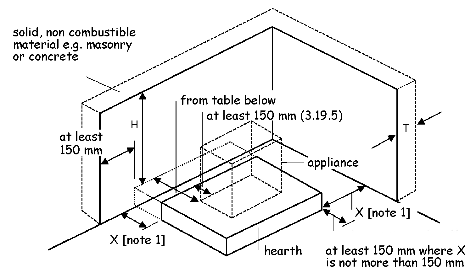
Table 3.12. Hearth and appliance adjacent to any part of a building
| Location of hearth or appliance | Thickness (T) of solid, non-combustible material | Height (H) of solid non - combustible material |
|---|---|---|
| Where the hearth abuts a wall and the appliance is not more than 50mm from the wall | 200mm | at least 300mm above the appliance or 1.2m above the hearth whichever is the greater. |
| Where the hearth abuts a wall and the appliance is more than 50mm but not more than 300mm from the wall | 75mm | at least 300mm above the appliance or 1.2m above the hearth whichever is the greater. |
| Where the hearth does not abut a wall and is not more than 150mm from the wall | 75mm | at least 1.2m above the hearth. |
Additional information:
There is no requirement for protection of the wall where X is more than 150mm.
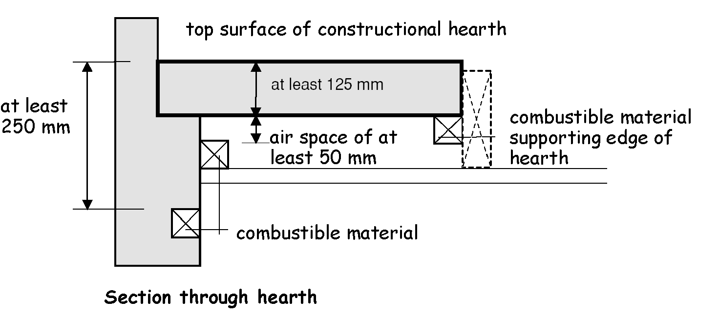
All combustible material under a constructional hearth should be separated from the hearth by an air space of at least 50mm. However an air space is not necessary where:
the combustible material is separated from the top surface of the hearth by solid, non-combustible material of at least 250mm, or
the combustible material supports the front and side edges of the hearth.
A fireplace recess should be constructed of solid, non-combustible material in accordance with the recommendations in clauses 7 and 8 of BS 8303: Part 1: 1994 and to the minimum thickness shown in Figure 2 to BS 8303: Part 3: 1994. The recess should incorporate a constructional hearth.
An alternative is to use a prefabricated appliance chamber of solid concrete components. These components should be:
supplied by the same manufacturer, with pre-made jointing arrangements, assembled on site using a cement specified for the purpose by the manufacturer, and
of insulating concrete with a density of between 1200 and 1700 kg/m3, and
installed on a constructional hearth, and
of components having a minimum thickness shown in the table below:
Table 3.13. Thickness of solid fuel appliance chamber components
| Component | Minimum thickness (mm) |
|---|---|
| Base | 50 |
| Sides | 75 |
| Back panel and top slab | 100 |
| Hood and bar lintels | 100 |