3.20 Combustion appliances – removal of products of combustion
|
The guidance to this standard includes design and construction issues relating to chimneys and flues. In 2010-11 Fire fighters attended 1565 chimney fires in Scotland. The main cause of these fires was inadequate maintenance of the chimneys, including routine cleaning of flues.
Combustion appliances fuelled by solid fuel, oil or gas all have the potential to cause carbon monoxide (CO) poisoning if they are poorly installed or commissioned, inadequately maintained or incorrectly used. Inadequate ventilation or a lack of the correct maintenance of appliances, flues and chimneys are the main causes of CO poisoning. Poisonous CO gas is produced when fuel does not burn properly. Incidents of poisoning can also occur through deterioration of the structure of the flue or chimney. Every year in Scotland there are fatalities from CO poisoning directly attributed to combustion appliances installed in buildings. In addition to these deaths there are also a considerable number of incidents where people are treated in hospital for the effects of CO poisoning. In some cases CO poisoning can result in serious and permanent injury to persons affected. Where CO gas may occur within a building early detection and warning can play a vital role in the protection and safety of the occupants. This is particularly important in buildings with sleeping accommodation.
Incorrect sizing of flues can also have serious repercussions. If a flue is too small, an insufficient volume of air will pass through it and this may lead to spillage of combustion gases. Too large a flue will slow down the flow of combustion gases and this may also lead to spillage.
The use of fanned flues allows combustion appliances to be located away from external walls. In such installations the flues can often be concealed within ceiling or wall voids making it difficult to determine whether the flue is still in good condition when an appliance is serviced or maintained.
Damaged or poorly maintained flues can allow CO gases to escape from the flue before the intended termination point. Therefore flues passing through a building should be minimised. Where it is not possible to avoid a flue passing through the building the route of the flue should be carefully considered to minimise the risk to occupants.
Conversions - in the case of conversions, as specified in regulation 4, the building as converted shall meet the requirement of this standard (regulation 12, schedule 6).
A chimney or flue-pipe serving any appliance should be suitable for use with the type of appliance served. A chimney should be manufactured using products in accordance with the following standards:
BS EN 1858: 2003, for concrete chimney blocks, or
BS EN 1806: 2000, for clay chimney blocks, or
BS EN 1857: 2003, for purpose made concrete flue linings, or
BS EN 1457: 1999, for purpose made clay flue linings, or
BS EN 1856-1: 2003, for a factory-made metal chimney, or
a lining accepted for the purpose after testing of the chimney under the relevant conditions by a notified body.
A flue in a chimney should be separated from every other flue and extend from the appliance to the top of the chimney. Every flue should be surrounded by non-combustible material that is capable of withstanding the effects of a chimney fire, without any structural change that would impair the stability or performance of the chimney. However the chimney may include a damp proof course (or courses) of combustible material.
A chimney or flue-pipe serving an oil-firing appliance should be constructed to the recommendations of BS 5410: Part 1: 1997 or OFTEC Technical Book 3 and OFTEC Standard OFS E106 as appropriate.
Satisfactory specification of chimneys and flue-pipes depends upon the gas temperature to be expected in normal service. Flue gas temperatures depend upon appliance types and the age of their design. Older appliances are likely to produce flue gas temperatures greater than 250ºC while modern boilers that bear the CE mark indicating compliance with the Boiler (Efficiency) Regulations 1993 will normally have flue gas temperatures less than 250ºC. Information for individual appliances should be sought from manufacturer’s installation instructions, from the manufacturers themselves or from OFTEC. Where this is not available, flues should be constructed for an assumed flue gas temperature of more than 250ºC.
High flue gas temperatures - where the flue gas temperatures are more than 250ºC, under normal working conditions, custom-built chimneys, system chimneys and flue-pipes should be designed and constructed for use with a solid fuel appliance.
Low flue gas temperatures - where the flue gas temperatures are not more than 250ºC, under normal working conditions, chimneys and flue-pipes may be of a lower specification as follows:
The flue gas temperatures are quoted in manufacturer’s product data and can be measured in accordance with OFTEC Appliance Standard OFS A100 for boilers, OFS A101 for cookers or OFS A102 for room heaters.
A chimney or flue-pipe should be constructed and installed in accordance with the following recommendations:
BS 5440-1: 2000
IGE/UP/7: Edition 2, ‘Gas Installation in timber framed and light steel framed buildings’, where the chimney or flue-pipe is in a timber frame building
the appropriate recommendations of the combustion appliance manufacturer, where the flue-pipe is supplied as an integral part of the combustion appliance.
There is an increased risk of carbon monoxide poisoning in bathrooms, shower rooms or rooms intended for use as sleeping accommodation, such as bed-sitters. Because of this, open-flued oil-firing appliances should not be installed in these rooms or any cupboard or compartment connecting directly with these rooms. Where locating a combustion appliance in such rooms cannot be avoided, the installation of a room-sealed appliance would be appropriate.
Regulation 30 of the Gas Safety (Installations & Use) Regulations 1998 has specific requirements for room-sealed appliances in these locations.
Metal chimneys should be guarded if there could be a risk of damage or if they present a risk to people that is not immediately apparent such as when they traverse intermediate floors out of sight of the appliance.
Where the metal chimney passes through a room or accessible space such as a walk-in cupboard it should be protected in accordance with the recommendations of:
BS EN 12391-1: 2003, for solid fuel appliances
BS 5410: Part 1: 1997, for oil-firing appliances
BS 5440: Part 1: 2000, for gas appliances.
It is not necessary to provide protection where a system chimney runs within the same space as the appliance served.
The size of a flue serving a solid fuel appliance should be at least the size shown in the table below and not less than the size of the appliance flue outlet or that recommended by the appliance manufacturer.
Table 3.11. Thickness of solid fuel appliance chamber components
| Appliance | Minimum flue size [3] |
|---|---|
| Fireplace with an opening more than 500mm x 550mm, or a fireplace exposed on 2 or more sides |
|
| Fireplace with an opening not more than 500mm x 550mm | 200mm diameter or rectangular/square flues having the same cross sectional area and a minimum dimension not less than 175mm |
| Closed appliance with rated output more than 30kW but not more than 50kW, burning any fuel | 175mm diameter or rectangular/square flues having the same cross sectional area and a minimum dimension not less than 150mm |
| Closed appliance with rated output not more than 30kW burning any fuel | 150mm diameter or rectangular/square flues having the same cross sectional area and a minimum dimension not less than 125mm |
| Closed appliance with rated output not more than 20kW that burns smokeless or low volatiles fuel | 125mm diameter or rectangular/square flues having the same cross sectional area and a minimum dimension not less than 100mm for straight flues or 125mm for flues with bends or offsets |
Additional information:
CLOSED APPLIANCE includes cookers, stoves, room heaters and boilers.
SMOKELESS FUEL means solid mineral fuel that produces combustion products containing particulate matter that does not exceed a specified low amount.
Any chimney pot or open-topped terminal must maintain the same cross-sectional area as the flue. Any covered terminal should have side outlets with a total free area twice that of the flue.
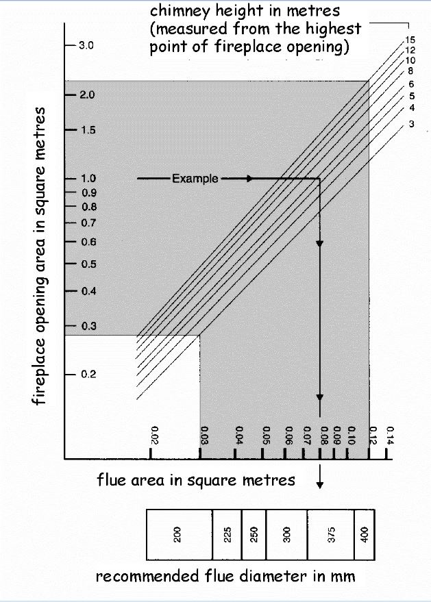
Specialist advice should be sought when proposing to construct flues with an area of more than 120000mm2 or 15% of the total face area of the fireplace opening.
The diagram to Figure 3.52 should only be used for the range of sizes shown within the shaded area.
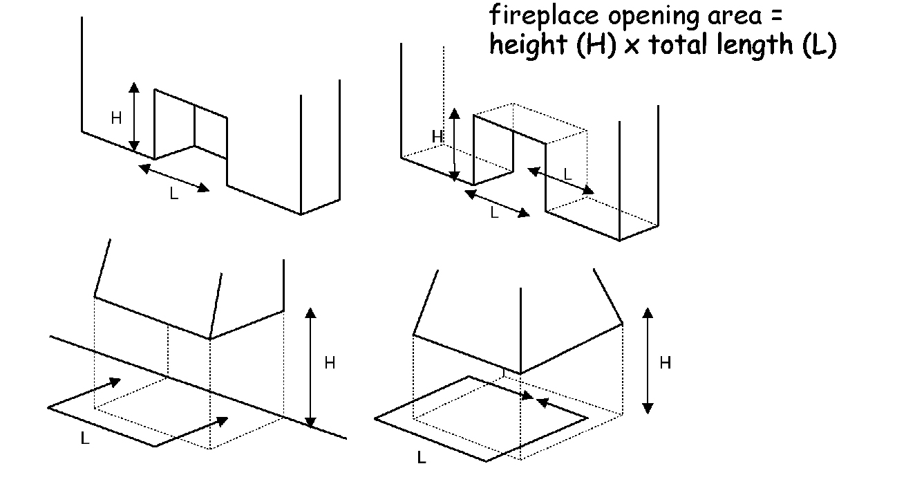
Fire size is related to the free opening area at the front of the fireplace opening.
The cross sectional area of a flue serving an oil-firing appliance should be in accordance with the recommendations in BS 5410: Part 1: 1997 and should be the same size as the appliance flue spigot.
The area of a flue serving a gas-fired appliance should have a size to ensure safe operation. A flue should be provided in accordance with the following recommendations:
Clause 9 of BS 5871: Part 3: 2005, for a decorative fuel-effect gas appliance
BS 5871: Part 2: 2005, for an inset live fuel-effect gas appliance
BS 5440: Part 1: 2000, for any other gas-fired appliance.
A combustion appliance should be connected to a chimney that discharges to the external air. However there are some combustion appliances that are designed not to discharge direct to the external air, such as flueless cookers. An opening window, extract fan or passive stack ventilation system may be sufficient to ventilate a kitchen but where other types of flueless appliances are installed, the manufacturer’s instructions should be followed.
Every solid fuel appliance should be connected to a separate flue.
Every oil-firing appliance should be connected to a separate flue. However this is not necessary where all the appliances have pressure jet burners and are connected into a shared flue.
Every gas-fired appliance that requires a flue should connect into a separate flue. However in certain instances, appliances can be connected to shared flues, if they are installed in accordance with the recommendations in BS 5440: Part 1: 2000.
The flue of a natural draught appliance, such as a traditional solid fuel appliance, should offer the least resistance to the passage of combustion gases. Resistance can be minimised by restricting the number of bends and horizontal runs should only be incorporated on back-entry appliances.
The horizontal length of the back-entry flue pipe at the point of discharge from the appliance should be not more than 150mm.
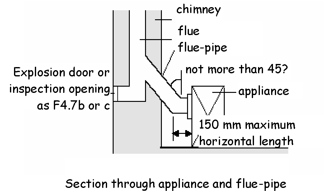
Where bends are essential, they should be angled at not more than 45º to the vertical.
The flue should have no intermediate openings. However it is acceptable to provide a draught stabiliser or draft diverter on the chimney provided it is in the same room or space as the appliance being served. An explosion door may also be provided.
Access should be provided for inspection and cleaning of the flue and the appliance and therefore an opening that is fitted with a non-combustible, rigid, gas-tight cover would be acceptable.
Adequate provision for inspecting flues that are positioned within a void, for example a service duct or above a suspended ceiling, should be provided. Such provisions will allow essential safety checks to be made by engineers when a combustion appliance is worked on, both during initial commissioning and any subsequent servicing.
Access hatches should be 300mm x 300mm or larger where necessary to allow sufficient access to the void to look along the length of the flue. The number and position of access hatches should allow the entire length of the concealed flue to be inspected with at least one hatch located within 1.5m of any joint in the flue system.
Access hatches are intended for inspection purposes only, it is not intended that they allow full physical access to the flue system.
To minimise the possibility of condensation in a metal chimney, it should not be fixed externally to a building, but should be routed inside the building. However a metal chimney may be fixed externally if it is insulated and constructed of a material that can be used externally, such as stainless steel or, in the case of gas, aluminium, so long as they conform to the specifications of the National Annex to BS EN 1856-1: 2003.
Combustion gasses at the point of discharge can be at a high temperature. Therefore flues discharging at low level where they may be within reach of people should be protected with a terminal guard.
A flue terminal should be protected with a guard if a person could come into contact with it or if it could be damaged. If the flue outlet is in a vulnerable position, such as where the flue discharges within reach of the ground, or a balcony, veranda or window, it should be designed to prevent the entry of matter that could obstruct the flow of gases.
The condensate plume from a condensing boiler can cause damage to external surfaces of a building if the terminal location is not carefully considered. The manufacturer’s instructions should be followed.
The outlet from a flue should be located externally at a safe distance from any opening, obstruction or flammable or vulnerable materials. The outlets should be located in accordance with the following diagram:
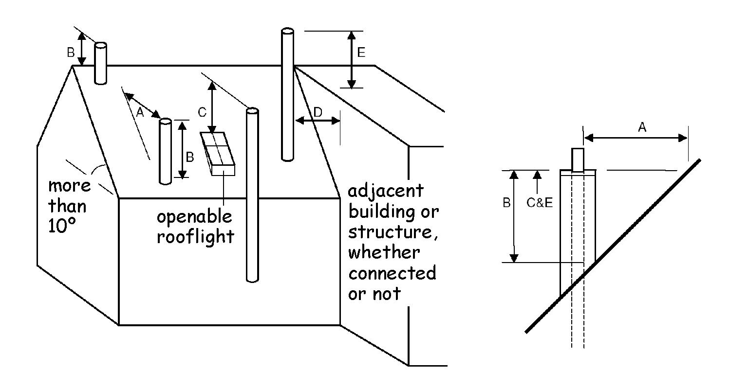
Table 3.12. Minimum dimension to flue outlets
| Location | Minimum dimension to flue outlets |
|---|---|
| A | 2.3m horizontally clear of the weather skin. |
| B | 1.0m provided A is satisfied or 600mm where above the ridge. However, where the roof is thatch or shingles, the dimensions should be as figure 3.53 to clause 3.20.17. |
| C | 1.0m above the top of any flat roof and 1.0m above any openable rooflight, dormer or ventilator, etc. within 2.3m measured horizontally. |
| D/E | Where D is not more than 2.3m, E must be at least 600mm. |
Additional information:
Flue terminals in close proximity to roof coverings that are easily ignitable, such as thatch or shingles, should be located outside Zones A and B in the following diagram:
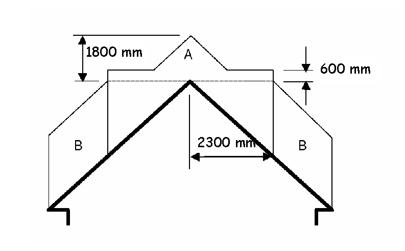
Table 3.13. Location of flue terminals relative to easily ignitable roof coverings
| Location | Location of flue terminals relative to easily ignitable roof coverings |
|---|---|
| Zone A | At least 1.8m vertically above the weather skin and at least 600mm above the ridge. |
| Zone B | At least 1.8m vertically above the weather skin and at least 2.3m horizontally from the weather skin. |
The outlet from a flue should be located externally at a safe distance from any opening, obstruction or combustible material. The outlets should be located in accordance with the following diagram:
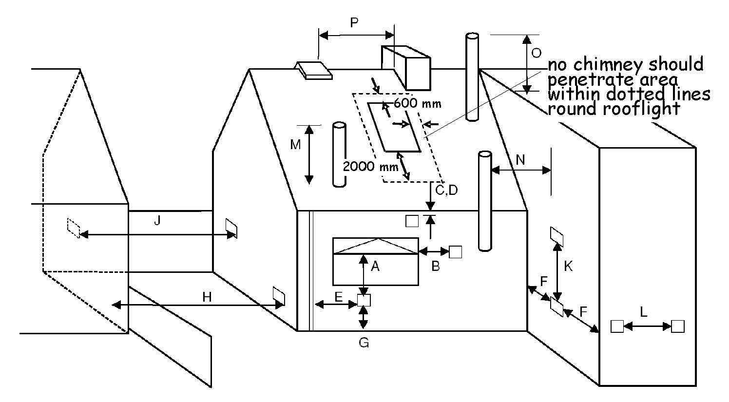
Table 3.14. Flue terminal positions for oil-firing appliances
| Location | Minimum distance to terminal (mm) | |
|---|---|---|
| pressure jet | vaporising | |
| A. Directly below an opening, air brick, opening window etc | 600 | not allowed |
| B. Horizontally to an opening, air brick, opening window etc | 600 | not allowed |
| C. Below a gutter, eaves or balcony with protection | 75 | not allowed |
| D. Below a gutter, eaves or balcony without protection | 600 | not allowed |
| E. From vertical sanitary pipework | 300 | not allowed |
| F. From an internal or external corner | 300 | not allowed |
| G. Above ground or balcony level | 300 | not allowed |
| H. From a surface or boundary facing the terminal | 600 [6] | not allowed |
| J. From a terminal facing the terminal | 1200 | not allowed |
| K. Vertically from a terminal on the same wall | 1500 | not allowed |
| L. Horizontally from a terminal on the same wall | 750 | not allowed |
| M. Above the highest point of an intersection with the roof | 600 [1] | 1000 [7] |
| N. From a vertical structure to the side of the terminal | 750 [1] | 2300 |
| O. Above a vertical structure not more than 750mm from the side of the terminal | 600 [1] | 1000 [7] |
| P. From a ridge terminal to a vertical structure on the roof | 1500 | not allowed |
Additional information:
Appliances burning Class D oil should discharge the flue gases at least 2m above ground level.
Terminating positions M, N, and O for vertical balanced flues should be in accordance with manufacturer’s instructions.
Vertical structure in N, O and P includes tank or lift rooms, parapets, dormers etc.
Terminating positions A to L should only be used for appliances that have been approved for low level flue discharge when tested in accordance with BS EN 303-1: 1999, OFS A100 or OFS A101.
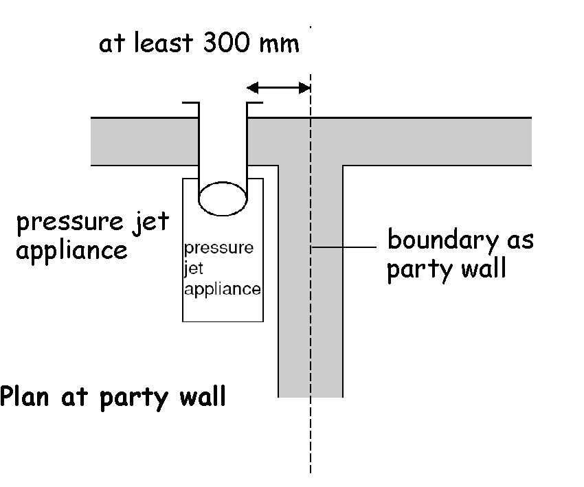
Terminating positions should be at least 1800mm from an oil storage tank unless a wall with a non-combustible construction type 7, short duration (see table to 2.B.1) and more than 300mm higher and wider each side than the tank is provided between the tank and the terminating position.
Where a flue terminates not more than 600mm below a projection and the projection is plastic or has a combustible finish, then a heat shield of at least 750mm wide should be fitted.
The distance from an appliance terminal installed at right angles to a boundary may be reduced to 300mm in accordance with diagram 2 to clause 3.20.16.
Where a terminal is used with a vaporising burner, a horizontal distance of at least 2300mm should be provided between the terminal and the roof line.
Notwithstanding the dimensions above, a terminal should be at least 300mm from combustible material.
The outlet from a flue should be located externally at a safe distance from any opening, obstruction or combustible material. The outlets should be located in accordance with the following diagram:
Table 3.15. Flue terminal positions for gas-fired appliances
| Location | Minimum distance to terminal in mm | |||
|---|---|---|---|---|
| Balanced flue, room-sealed appliance | Open flue | |||
| natural draught | fanned draught | natural draught | fanned draught | |
| A. Directly below an opening, air brick, opening window, etc. | (0-7 kW) 300 (>7-14 kW) 600 (>14-32 kW) 1500 (>32-70 kW) 2000 |
300 | n/all | 300 |
| B. Above an opening, air brick, opening window, etc. | (0-32 kW) 300 (>32-70 kW) 600 |
300 | n/all | 300 |
| C. Horizontally to an opening, air brick, opening window, etc. | (0-7 kW) 300 (>7-14 kW) 400 (>14-70 kW) 600 |
300 | n/all | 300 |
| D. Below a gutter, or sanitary pipework | 300[2] | 75[1] | n/all | 75[1] |
| E. Below the eaves | 300[2] | 200 | n/all | 200 |
| F. Below a balcony or carport roof | 600 | 200 | n/all | 200 |
| G. Above ground, roof or balcony level | 300 | 300 | n/all | 300 |
| H. From vertical drain/soil pipework | 300 | 150[3] | n/all | 150 |
| J. From an internal or external corner | 600 | 300 | n/all | 200 |
| K. From a surface or boundary facing the terminal [4] | 600 | 600[5] | n/app | 600 |
| L. Vertically from terminal on same wall | 1500 | 1500 | n/app | 1500 |
| M. Horizontally from terminal on same wall | 300 | 300 | n/app | 300 |
| N. From a terminal facing the terminal | 600 | 1200[6] | n/app | 1200 |
| P. From an opening in a carport (e.g. door, window) into the building | 1200 | 1200 | n/app | 1200 |
| R. From a vertical structure on the roof [7] | n/app | n/app | [note 8] | n/app |
| S. Above an intersection with the roof | n/app | [note 9] | [note 10] | 150 |
Additional information:
Notwithstanding the dimensions in the table, a terminal serving a natural draught and fanned draught appliance of more than 3kW heat input, should be at least 300mm and 150mm respectively from combustible material.
Where a natural draught flue terminates not more than 1m below a plastic projection or not more than 500mm below a projection with a painted surface, then a heat shield at least 1m long should be fitted.
This dimension may be reduced to 75mm for appliances of up to 5kW heat input.
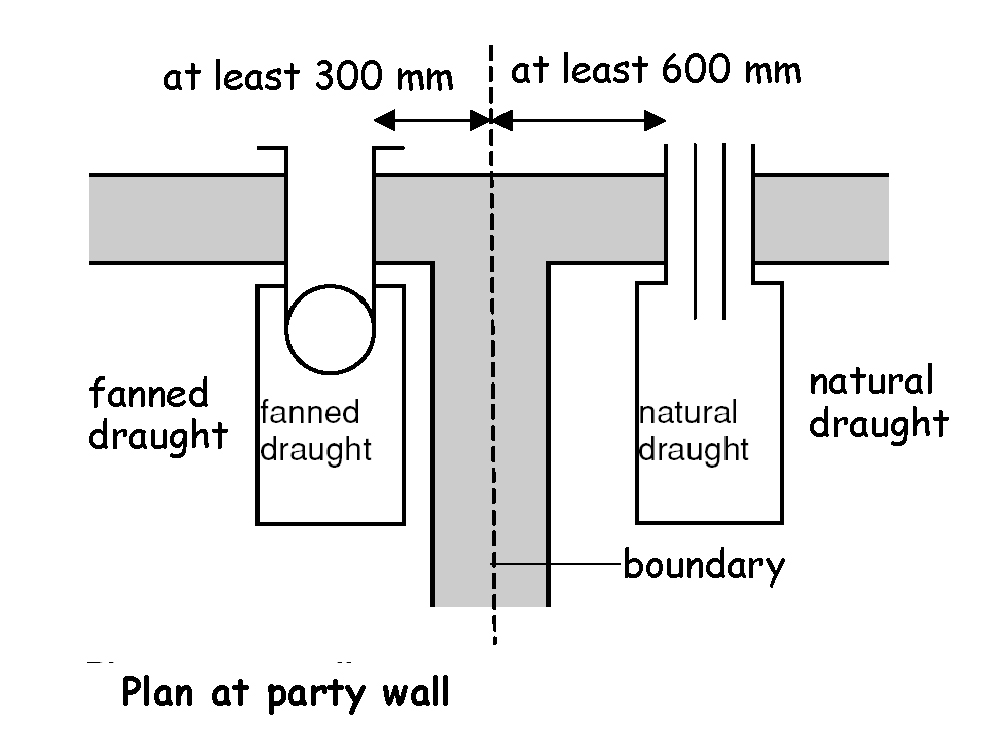
The products of combustion should be directed away from discharging across a boundary.
The distance from a fanned draught appliance terminal installed at right angles to a boundary may be reduced to 300mm in accordance with diagram 2 to clause 3.20.17.
The distance of a fanned flue terminal located directly opposite an opening in a building should be at least 2m.
Vertical structure includes a chimney-stack, dormer window, tank room, lift motor room or parapet.
1500mm if measured to a roof terminal, otherwise as Table 2 in BS 5440-1: 2000.
To manufacturer’s instructions.
As Table 2 in BS 5440-1: 2000.
n/all = not allowed. n/app = not applicable.
Carbon monoxide (CO) is a colourless, odourless, and tasteless gas. Low levels of CO gas can be present in the atmosphere, however, it is highly toxic and dangerous to humans and animals in higher quantities. The gas is produced in high levels from appliances where incomplete combustion of a carbon based fuel occurs. Incomplete combustion could occur in appliance installations that are defective, lack proper maintenance or have inadequate provision for combustion air.
In order to alert occupants to the presence of levels of carbon monoxide which may be harmful to people, a detection system should be installed in all dwellings where:
a new or replacement fixed combustion appliance (excluding an appliance used solely for cooking) is installed in the dwelling, or
a new or replacement fixed combustion appliance is installed in an inter-connected space, for example, an integral garage.
Carbon monoxide detectors should comply with BS EN 50291-1:2010 and be powered by a battery designed to operate for the working life of the detector. The detector should incorporate a warning device to alert the users when its working life is due to expire. Hard wired mains operated carbon monoxide detectors complying with BS EN 50291-1:2010 (Type A) with fixed wiring (not plug in types) may be used as an alternative, provided they are fitted with a sensor failure warning device.
Where carbon monoxide detectors are within the scope of either or both:
European Directive 2006/95/EC – Low Voltage Directive, and/or
European Directive 1999/5/EC – Radio and Telecommunication Terminal Equipment Directive
they should be constructed to fully comply with all applicable safety aspects of the Directive(s).
The guidance in this clause takes account of the audibility levels in adjoining rooms and the effect of carbon monoxide moving throughout the building. Carbon monoxide detectors should include an integral sounder.
A carbon monoxide detection system to alert occupants to the presence of carbon monoxide should consist of at least:
1 carbon monoxide detector in every space containing a fixed combustion appliance (excluding an appliance used solely for cooking), and
1 carbon monoxide detector to provide early warning to high risk accommodation, that is, a bedroom or principal habitable room, where a flue passes through these rooms.
Unless otherwise indicated by the manufacturer, carbon monoxide detectors should be either:
ceiling mounted and positioned at least 300mm from any wall, or
wall mounted and positioned at least 150mm below the ceiling and higher than any door or window in the room.
Carbon monoxide detectors in the space containing the combustion appliance should be sited between 1m and 3m from the appliance.
Note: where the combustion appliance is located in a small space it may not be possible to locate the detector within that space. In such circumstances the detector may be located at the appropriate distance outwith the space.
A carbon monoxide detector should not be sited:
in an enclosed space (for example in a cupboard or behind a curtain)
where it can be obstructed (for example by furniture)
directly above a sink
next to a door or window
next to an extract fan
next to an air vent or similar ventilation opening
in an area where the temperature may drop below -10°C or exceed 40°C, unless it is designed to do so
where dirt and dust may block the sensor
in a damp or humid location, or
in the immediate vicinity of a cooking appliance.
Additional guidance on the siting of carbon monoxide detectors, including enhanced coverage, can be found in BS EN 50292:2002.
The provision of a carbon monoxide detection system should not be regarded as a substitute for the correct installation and regular servicing of a combustion appliance.