Assessment of electrolysers: report
An assessment into the state of electrolyser manufacturing globally, to support an understanding of the supply chain opportunities in Scotland.
1. Introduction to Electrolysers
Commitments on the use of hydrogen to enable the transition to a low carbon energy system have accelerated globally over the past few years. In 2020, the Scottish Government published the Hydrogen Policy Statement[1] that sets out Scotland's ambition for hydrogen in the energy transition, aiming for 5GW of installed hydrogen capacity by 2030 and 25GW by 2045. The draft Hydrogen Action Plan[2], published in 2021, sets out the specific actions required to meet the targets defined in the policy statement, including addressing high production costs, securing economic benefit from public and private sector investment, growing the hydrogen sector in Scotland and the creation of regional hydrogen hubs. The UK Government has also announced hydrogen targets that were recently increased from 5GW to 10GW of low carbon hydrogen production by 2030, with at least half of that being electrolytic, as set out in the UK Hydrogen Strategy[3] and Energy Security Strategy[4].
Scotland's vast renewable resources, including onshore and offshore wind, wave and tidal energy, makes it particularly suitable for the early deployment of electrolytic hydrogen technology with a potential to position itself at the forefront of a growing global industry. The recent ScotWind offshore leasing round will add nearly 25GW of new offshore wind capacity, which could lead to significant scaling up of electrolytic hydrogen production over the next decade. The potential scale of the electrolytic hydrogen market in Scotland was recently illustrated in the Scottish Hydrogen Assessment[5], developed by Arup and E4Tech, in which the most ambitious scenario establishing Scotland as an exporter of green energy to Europe could result in 126 Terawatt hours (TWh) of green hydrogen production, a £25 billion contribution to Gross Value Added (GVA) and over 300,000 jobs by 2045. This is dependent on unlocking Scotland's offshore wind potential and developing policy that provides positive signals to industry to produce electrolytic hydrogen that can supply growing domestic demand in the UK and is also competitive in the European market.
Meeting Scotland's hydrogen ambitions in a way that targets long-term decarbonisation will require considerable scaling of electrolytic hydrogen technologies which, in turn, will require a robust electrolyser supply chain. If developed early in Scotland, an electrolyser supply chain could create skilled jobs and generate significant investment in the Scottish economy. Establishing an electrolyser supply chain could also make Scotland an early mover in the export of electrolysers as demand for electrolytic hydrogen is expected to increase significantly in the coming decade.
The purpose and structure of this report
The Scottish Government has commissioned Arup to produce this report to investigate the electrolyser supply chain capabilities and opportunities for Scotland. The remainder of Section 1 sets out the context of electrolysers within the wider hydrogen system and gives an overview of the three electrolyser technologies that are the focus of this report, in addition to some emerging technologies. Section 2 provides a critical component analysis and assesses the capabilities required at each stage of the supply chain. In Section 3, a targeted literature review on the current state of the electrolyser supply chain market, globally and locally, is provided to give a view of where Scotland sits within the wider market and the opportunities for growth. The critical component analysis and supply chain market review, along with input from key Scottish stakeholders, comes together in Section 4 to assess the opportunities for Scotland. Finally, suggested next steps to support Scotland's skills and supply chain strengths over the coming years are provided in Section 5.
1.1 The role of electrolysers within the hydrogen system
Hydrogen as an energy carrier can support a more flexible, resilient and integrated energy system, complementing increasing electrification. It offers opportunities for long-term decarbonisation of hard to abate sectors such as heat, transport and industry, where electrification may not be suitable due to technical, economic or geographical constraints.
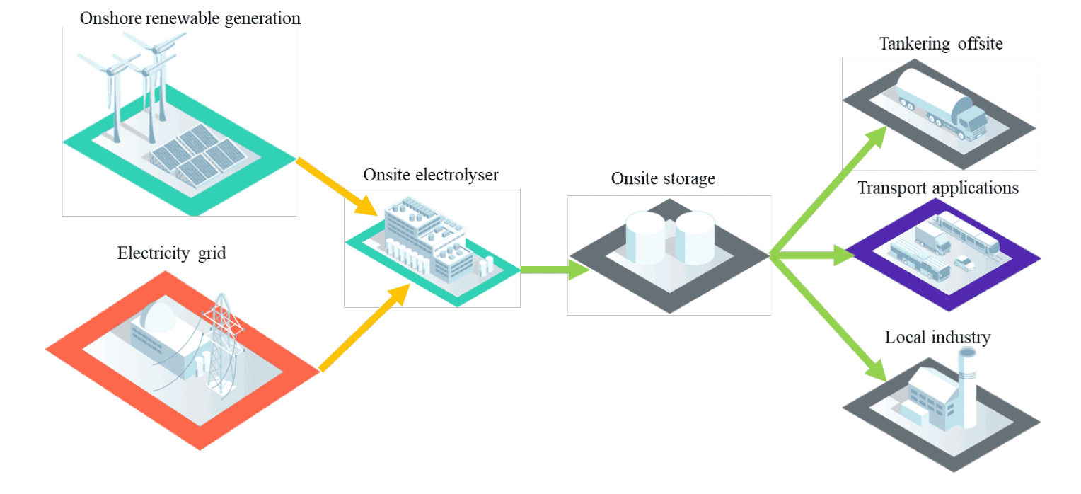
Figure 1 shows the overall hydrogen energy system, with electrolytic hydrogen production highlighted in green. Electrolytic hydrogen is produced by applying electricity to split a pure water source into its component molecules of hydrogen and oxygen. Electrolysers, or more precisely electrolyser stacks, are the primary electrochemical component in an electrolytic hydrogen production system. Electrolyser stacks are the main component within an electrolyser system and are supported by auxiliary components required for functions such as water and electricity supply, cooling and purification. The hydrogen produced from the electrolyser stack is purified through separation and drying processes, whilst oxygen is released into the atmosphere or can be captured or stored to supply other industrial processes. Hydrogen can be used directly to produce electricity via a fuel cell (which can be used in power or transport applications) or combusted to produce heat. It can also be stored in either gas or liquid form and later used for power generation to smooth peaks in energy demand. In the future hydrogen may be injected into the gas national transmission system, providing a low carbon replacement for natural gas, although this is dependent on legislation on blending being approved. The UK Government's Ten Point Plan aims to complete testing necessary to allow up to 20% blending of hydrogen into the gas distribution grid by 2023[6].
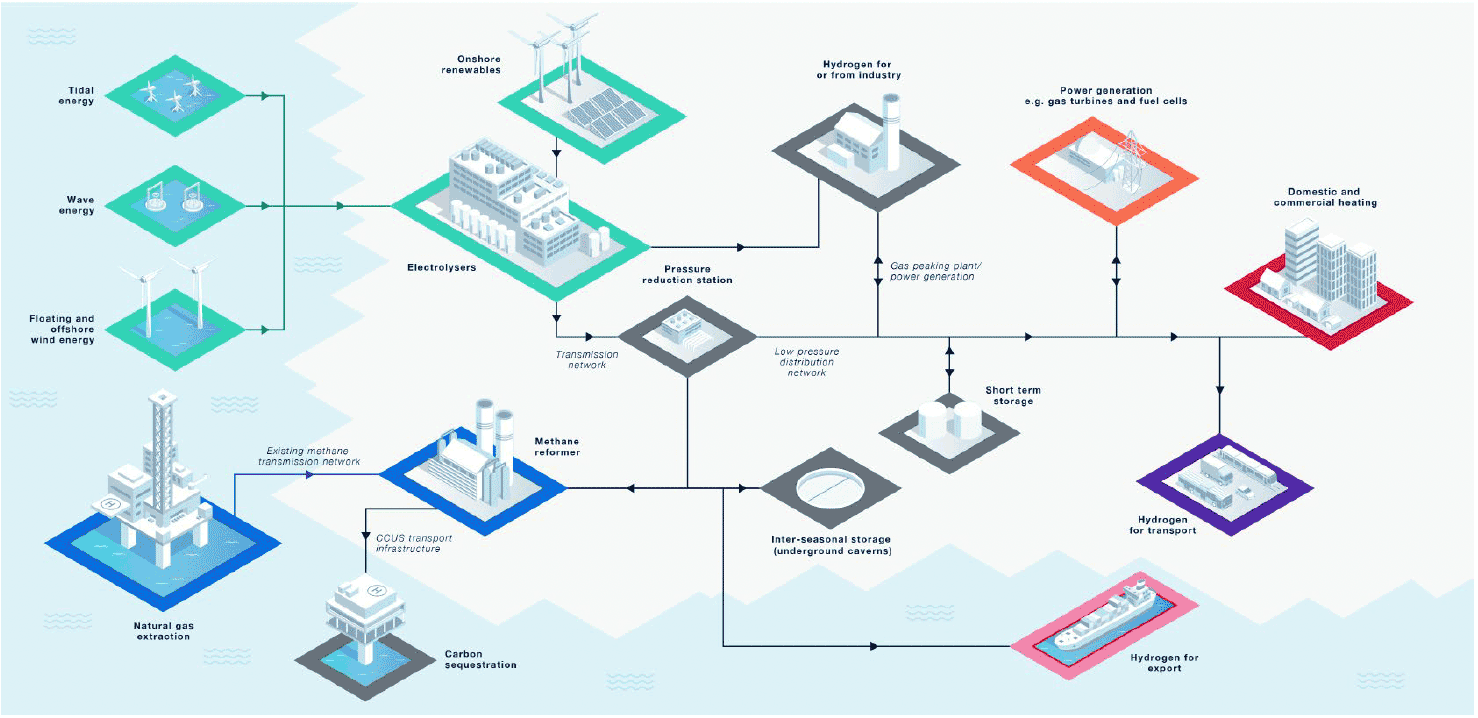
A key advantage to electrolytic hydrogen, as opposed to carbon capture, utilisation and storage (CCUS) enabled hydrogen produced from natural gas, is that it does not produce emissions at point of production. Electrolysis also complements the increasing renewable energy capacity in Scotland by enabling surplus electricity production to be utilised for hydrogen production instead of being curtailed at high cost to the electricity network. However, electrolysis is currently the most expensive method of hydrogen production, although this is predicted to decrease over the coming years due to economies of scale and renewable electricity becoming cheaper.
As shown in Figure 1, electrolytic hydrogen can be produced from a range of electricity sources including direct grid connection, direct connection to renewables or a hybrid of grid/direct connected electricity. Only direct connection to a renewable energy source guarantees zero carbon electricity, however, the impact of grid emissions on hydrogen production is expected to decrease over the next decade as more renewable generation is connected to the national grid. Increasingly, offshore hydrogen production at offshore wind sites is being investigated, which will require significantly more pipework to transport hydrogen to the point of use.
1.1.1 Hydrogen production archetypes
A future electrolytic hydrogen production system could have several different archetypes depending on the scale of the system, whether it is located on or offshore and whether the production of hydrogen is centralised or decentralised. The mix of archetypes is uncertain at this stage, but could be combination of some of the following:
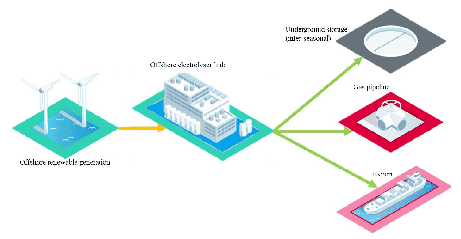
Large-scale offshore production
Hydrogen could be produced offshore either on centralised platforms or within individual turbines utilising the large offshore wind potential of Scotland. These systems are likely to range from 100s Megawatts (MW) up to several GW in size. This type of production is likely to be led by the offshore wind developers. These systems can either transport the gas onshore through new or existing pipes, supply hydrogen direct to offshore underground storage or be exported around the UK and Europe directly from an energy island. Figure 2 shows such a system.
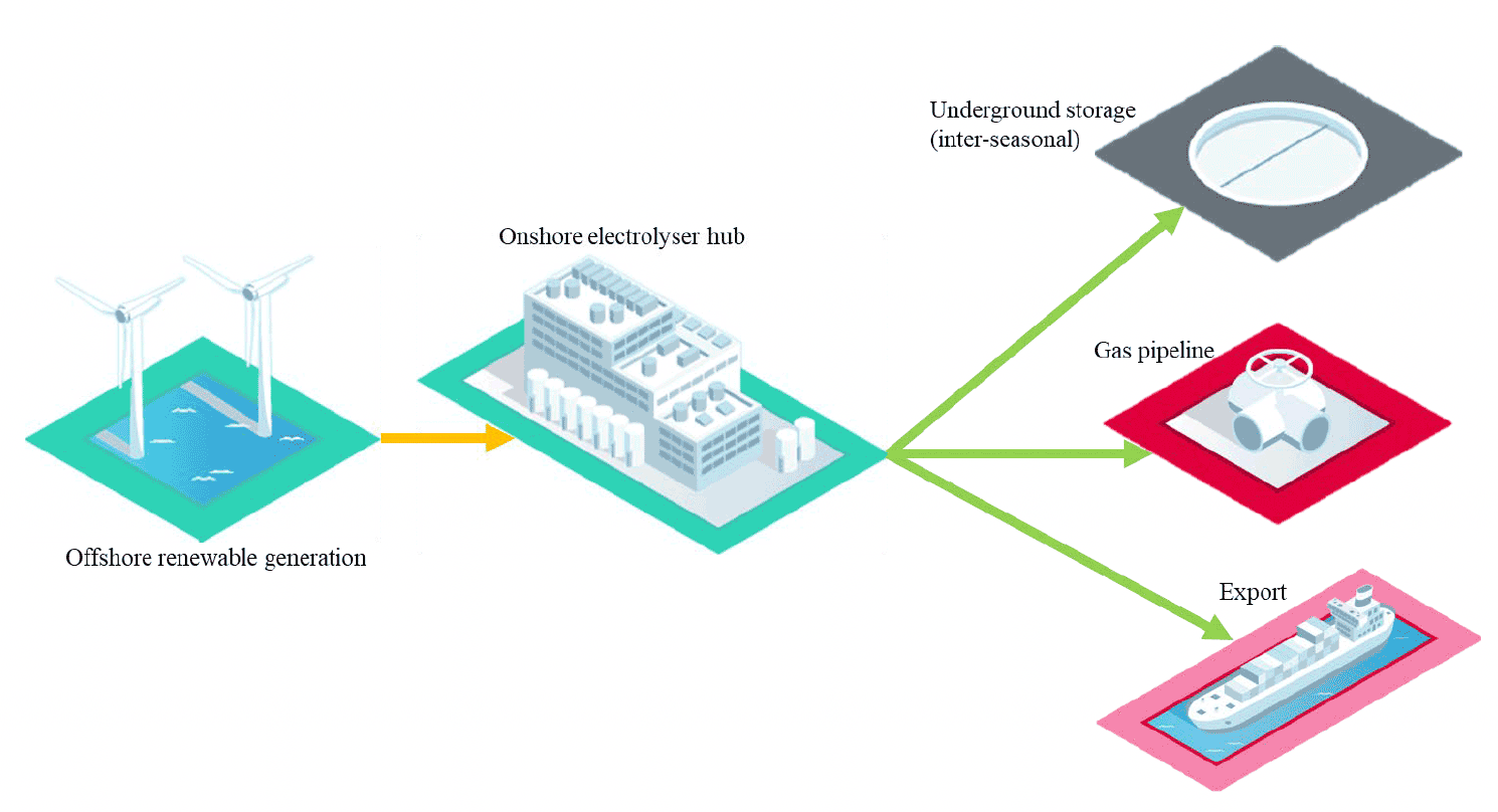
Large-scale onshore production from offshore wind
If the electrical network is sufficiently robust, offshore wind developers may choose to land electricity rather than hydrogen. In this case, large-scale production could be located around the coastal areas of Scotland taking advantage of the electricity that is coming ashore and supporting the grid network during times of constraint. These systems are likely to range from 100s MW up to several GW in size. As with offshore production, this hydrogen could then be transported through new or existing pipes, supply hydrogen direct to offshore underground storage or be exported around the UK and Europe through nearby port facilities. Figure 3 shows such a system.
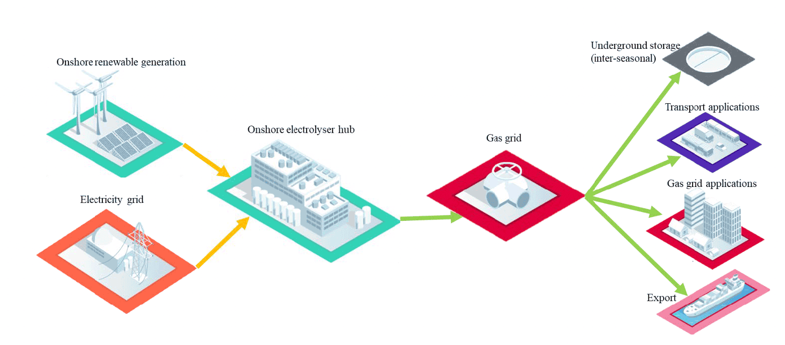
Large-scale centralised production
Hydrogen production could become centralised in key areas that have an excess of the critical components for electrolyser deployment, electricity and water. These areas would have access to a high-capacity electricity grid connection or/and a direct connection to onshore renewables like wind or solar PV. Due to their grid links, they could operate at their maximum output to ensure consistent production. These systems are likely to range from 100s MW up to GW in size. It is likely that centralised production would be transported via pipelines to either large-scale storage facilities, demand centres or export terminals. Figure 4 shows such a system.
Small-scale decentralised production
There are several different models of decentralised hydrogen production. These systems could be fed from local renewable energy systems to service local industrial demand (e.g. distilleries) or they could be located in urban areas and connected to the electricity grid to provide local hydrogen production and resilience for transport hubs. These systems will likely be from a few MW up to low 100s of MW in size. It is likely that these will also require some form of local storage. Figure 5 shows such a system.
1.2 Electrolyser technologies
Electrolyser stacks are comprised of two electrodes (a positively charged anode and a negatively charged cathode) that are separated by an electrolyte, which is the media responsible for transporting the chemical charges (ions) from one electrode to the other. A variety of electrolyser technologies exist that each present their own opportunities and potential challenges. For this study, the technologies with highest maturity will be covered in detail, whilst the more novel technologies will be briefly described. The electrolyser technologies that have systems proven in an operational environment, the equivalent of a technology readiness level (TRL) of 9, are proton exchange membrane (PEM), pressurised alkaline (ALK) and solid oxide electrolysers (SOE). It should be noted that although the technology behind these systems is proven at smaller scale, all three of the technologies must be commercially deployed at larger scales to be considered fully mature. Table 1 summarises the main properties of these electrolysers.
Table 1: Electrolyser Technologies
Technology: PEM
Electrolyte: Solid polymer
Operating Temperature: <100 ℃
System Efficiency: c. 60%
Opportunities:
Compact size
High purity hydrogen (no need for additional purification).
Operates at 30bar pressure (no need for additional compression for some applications).
Solid electrolyte (reduces corrosion and gas leakage).
Flexible operation makes it suitable for direct connection with intermittent renewables.
Potential Challenges:
Expensive precious metal catalyst (i.e. platinum) increases the cost.
Can be sensitive to impurities therefore feed water must be high purity.
Technology: ALK
Electrolyte: Potassium or sodium hydroxide (liquid)
Operating Temperature: <100 ℃
System Efficiency: c. 60%
Opportunities:
Widely available and lower cost.
Nickel catalyst is a low-cost non-precious metal component.
Quick start up makes it suitable for direct connection with intermittent renewables.
Stable operation suitable for large-scale production.
Potential Challenges:
Liquid electrolyte can increase maintenance required due to corrosion.
Medium purity hydrogen (further purification required for some end uses).
Low operating pressure (requires additional compression).
Can be sensitive to impurities therefore feed water must be high purity.
Technology: SOE
Electrolyte: Solid ceramic
Operating Temperature: 500-850 ℃
System Efficiency: 80-90%
Opportunities:
High efficiency as it can withstand high temperature operation.
Solid electrolyte (reduces corrosion and gas leakage).
Does not require precious metals.
Less sensitive to impurities therefore lower purity water can be used.
Suitable for steady operations with a nearby (waste) heat source (e.g. nuclear).
Heat can be utilised (e.g. in gas turbine) to improve efficiencies.
Potential Challenges:
Long start up time (≥ 12 hours) and ceramic parts cannot withstand heating/cooling cycles very well (limited number of shutdowns) therefore unsuitable for flexible operations.
1.2.1 Proton Exchange Membrane (PEM)
A PEM electrolyser stack consists of electrodes separated by a solid polymer electrolyte, which is responsible for transporting ions from anode to cathode whilst physically separating the generated hydrogen and oxygen gas.
The polymer electrolyte allows a fast response to load changes and close to 100% turndown capability. This means that PEM electrolysers can ramp hydrogen production up and down to meet a variable demand. This flexible demand response makes the PEM electrolyser particularly suitable for intermittent renewable energy applications, including curtailed electricity consumption. Their compact size would also make PEM electrolysers highly suitable for offshore locations.
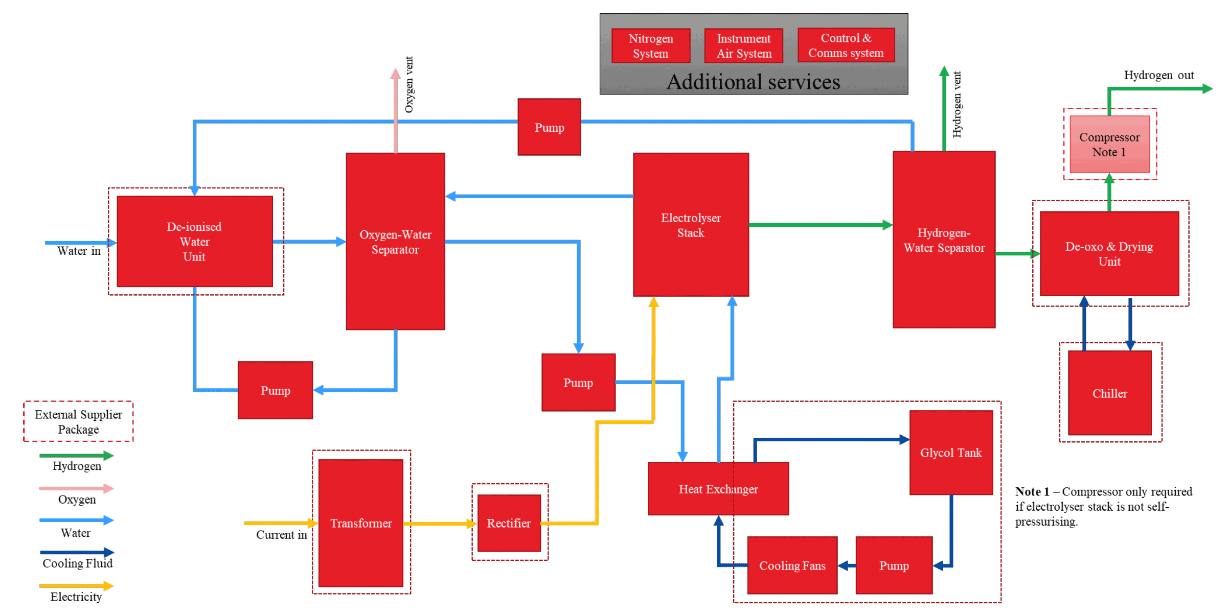
Figure 6 shows the process flow diagram for a PEM electrolyser, including all the auxiliary components (such as coolers and dryers) associated with a complete system. As well as the electrolyser stack, components are required to supply the input water and electricity, cool the system as required and purify the outputs from the stack.
1.2.2 Pressurised Alkaline (ALK)
Similar to PEM electrolysis, ALK electrolyser stacks consist of two electrodes, however, the electrolyte is in a liquid form and the electrodes and generated gas are physically separated via a porous inorganic diaphragm, also known as separator. The liquid electrolyte is typically a highly concentrated potassium hydroxide solution that is responsible for transporting ions.
ALK electrolysers are the most mature technology, and their long-term stability allows them to be used in industry for the large-scale production of hydrogen for different end uses. ALK electrolysers present the simplest stack and system design, which translates to ease of manufacture and is ultimately the cheapest electrolysis technology, however, the design is not as compact as PEM electrolysers.
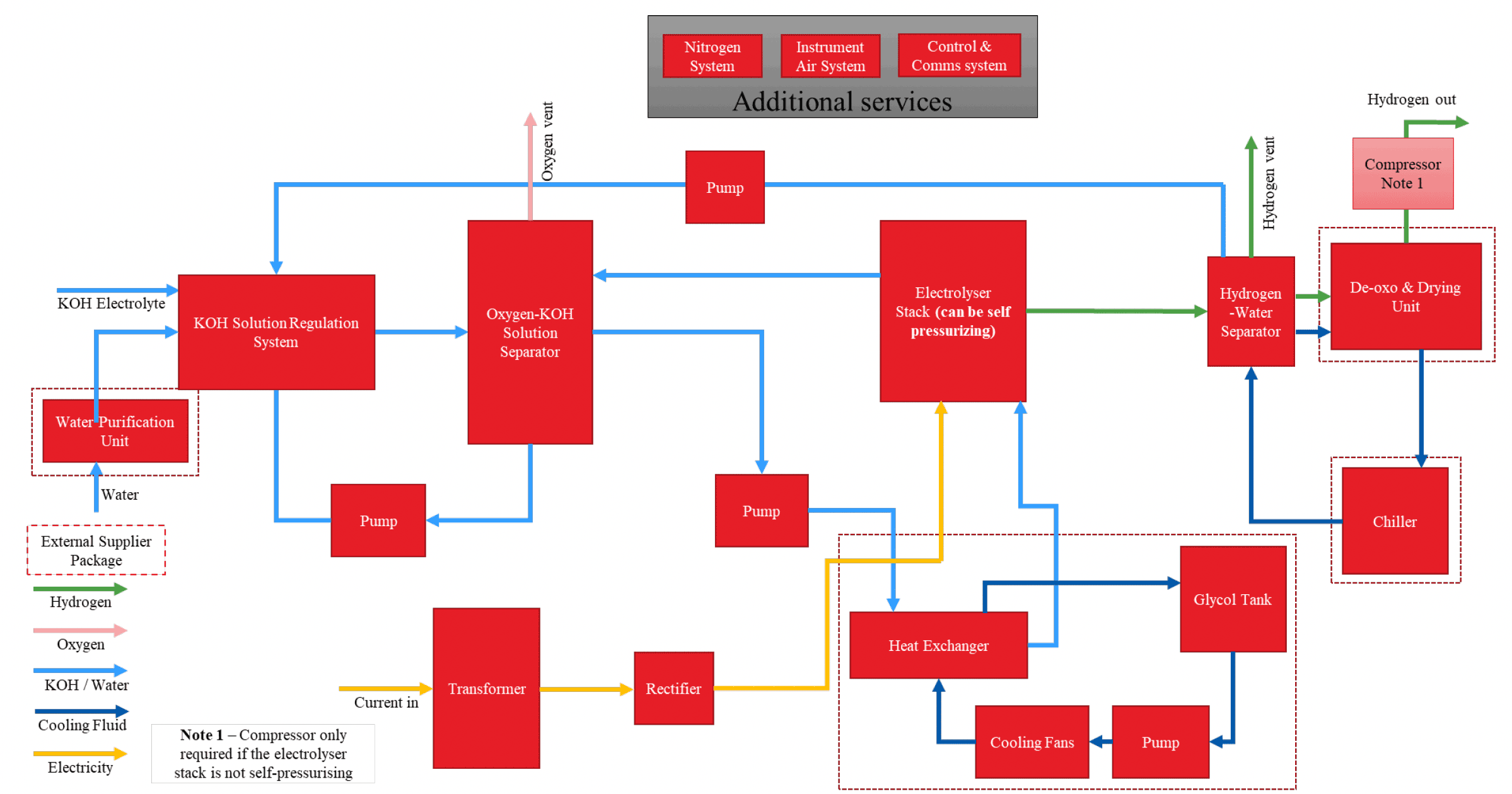
Figure 7 shows the process flow diagram for an ALK electrolyser including all the auxiliary components associated with a complete system. As well as the electrolyser stack, the system includes key components required to supply the input water and mix it with the potassium hydroxide electrolyte, supply the input electricity, cool the system as required and purify the outputs from the stack.
1.2.3 Solid Oxide Electrolyser (SOE)
SOEs differ from PEM and ALK electrolysers as they utilise heat to make hydrogen from steam. SOE electrolyser stacks are made from a mix of ceramics and metal that can handle very high temperatures of >500°C.
SOEs are best placed where there is a waste heat source available (e.g. nuclear or industrial facilities) as it can utilise this heat to reduce the electrical requirement to produce hydrogen. The main advantage of SOEs is their high system efficiency of 80-90%, if waste heat can be used. There is also an opportunity to capture and use the excess heat from electrolysis to improve efficiency further. However, SOEs are not able to ramp up and down very quickly due to the high temperatures involved, therefore are better suited to base load requirements.
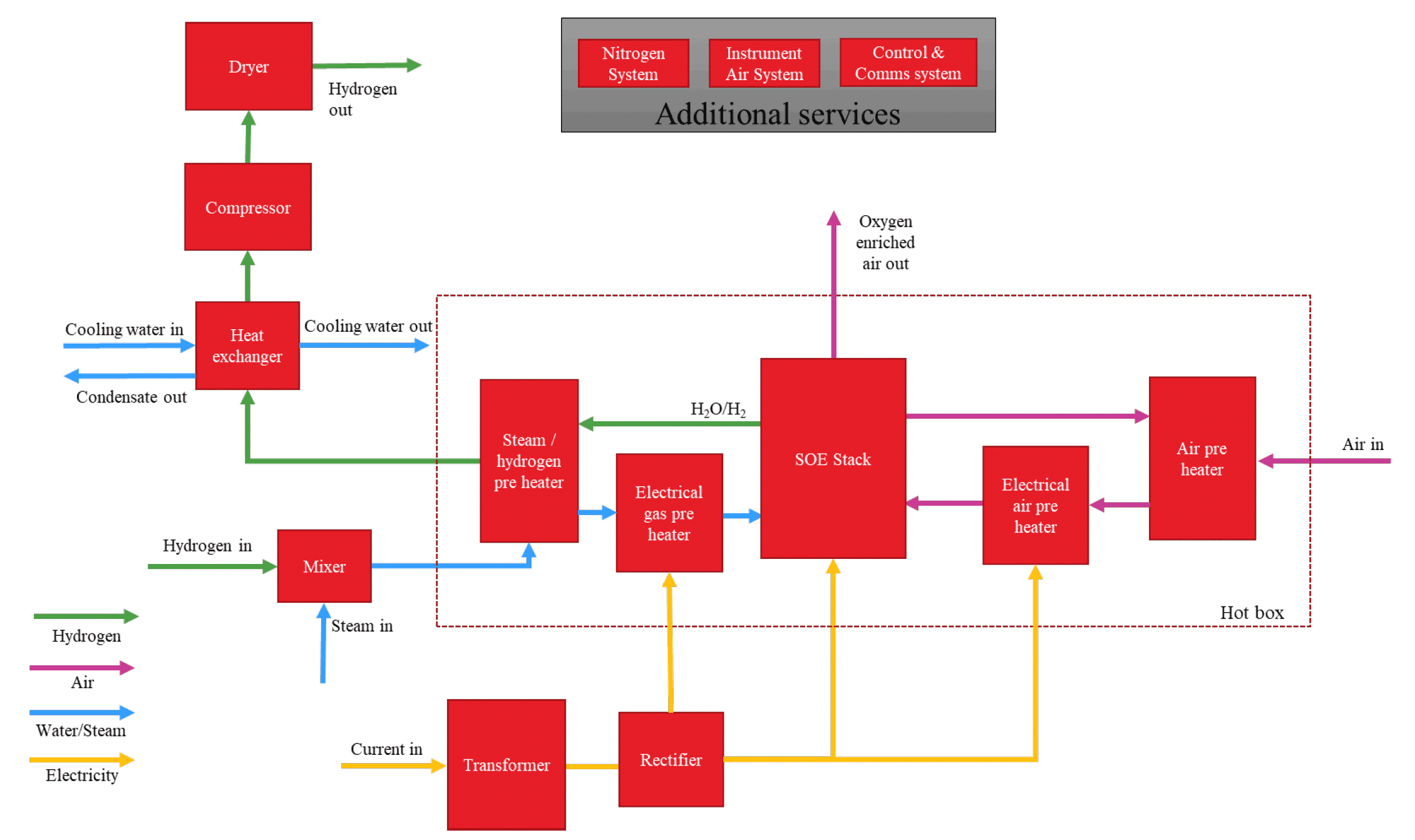
Figure 8 shows the process flow diagram for an SOE including all the auxiliary components associated with a complete system. As well as the electrolyser stack, the system includes key components required to supply the input water and mix it with the potassium hydroxide electrolyte, supply the input electricity, cool the system as required and purify the outputs from the stack.
1.2.4 Innovative technologies in development
There is a small number of electrolyser technologies that are currently in development and therefore will not be explored in detail for the scope of this supply chain study. However, a short summary of these technologies is provided below for awareness, as they may be of interest in the future should they reach commercial scale.
- Anion Exchange Membrane (AEM): The AEM electrolyser uses an aqueous solution of 1% potassium hydroxide as the electrolyte. The liquid electrolyte only circulates in the anode side, while the cathode side remains dry. Therefore, the hydrogen produced from the cathode half-cell has a low moisture content. AEM electrolysers produce high purity hydrogen due to a pressure difference preventing oxygen from crossing over. These systems have been demonstrated in relevant environments and are therefore TRL 6.
- Membrane-Less Electrolysis: A membrane-less electrolyser as an alternative to PEM electrolysers is currently in development. This allows hydrogen to be produced using intermittent renewable electricity with no drop in performance that is associated with membrane technologies. The mixed gas that is produced is immediately cooled using a cryogenic system to separate the hydrogen and oxygen. These systems have been demonstrated in relevant environments and are therefore TRL 6.
- Thermolysis: Thermolysis involves the splitting of water by applying extremely high temperatures of 500-2,000°C (for example, from concentrated solar power or nuclear reactions). The reaction is achieved using chemical cycles, such as cerium oxide or copper chloride, which reuse the chemicals in a closed-loop process. Challenges include the cost of producing high temperature heat and the durability of materials involved. These systems have been validated in the lab and are therefore TRL 4.
1.3 Suitability of electrolyser for large-scale hydrogen production
In 2020, only c. 0.03% of hydrogen production for energy and feedstocks came from water electrolysis[7], therefore significant increase in the manufacture and deployment of electrolysers will be required to enable large-scale electrolytic hydrogen production.
Electrolysers are generally modular and therefore scalable to the size of generation they are linked to, however, this can be limited by grid/renewable capacity constraints or limitations in the supply chain. Suppliers are taking different approaches to scaling up electrolyser capacity; while some are looking to increase capacity of the stack itself, others plan to combine several stacks to increase overall production capacity.
Current electrolyser projects generally have capacities of 1-10MW, which is forecast to increase to 100-500MW by 2025 and 1GW+ by 2030[8]. Iberdrola S.A. currently operates Europe's biggest electrolytic hydrogen facility in Spain, with a capacity of 20MW, while Shell has recently announced investment in a 200MW facility in Rotterdam planned for 2025. Globally, there is already strong interest in future GW-scale green hydrogen projects, for example, Intercontinental Energy are planning one of the world's largest renewable energy and green hydrogen hubs in Australia at 26GW with BP recently buying a stake in the project.
The varying properties of the three electrolyser technologies make them suitable for different types of production and scale-up opportunities. Table 2 outlines the production suitability of each electrolyser, along with the key supporting components required. In general PEM and ALK have a similar system set-up, however, SOE equipment differs due to the use of steam instead of feed water in the process.
Table 2: Production suitability and generic components of electrolyser types
Technology: PEM
Production Suitability:
Modular with unit sizes ranging from 1MW to 17.5MW.
Can be used from small-scale systems through to large-scale.
No obvious barriers to offshore usage.
Not fully mature technology implies potential lower availability of components.
Generic Components:
Feed Water Supply
Rectifier
Pumps
Hydrogen Dryer
Cooling System
Compressor (for certain applications)
Technology: Pressurised ALK
Production Suitability:
Modular with unit sizes ranging from 500kW to 5MW.
Can be used from small-scale systems through to large-scale.
Used in submarines so offshore usage should not be an issue.
Atmospheric alkaline systems have high reliability.
Pressurised systems have lower reliability in comparison to a PEM.
Generic Components:
Feed Water Supply
Rectifier
Pumps
Hydrogen Dryer
Cooling System
Compressor (for certain applications)
Technology: SOE
Production Suitability:
Becoming more modular as more manufacturers explore the technology.
Currently at a lower stage of development and only used at small-scale due to cost.
Offshore usage likely to be less suitable due to heat source required.
Needs to be coupled with high waste heat process to achieve efficiencies.
Generic Components:
Rectifier
Pumps
Compressor
Contact
Email: hydrogeneconomy@gov.scot