Unintended overexposure of a patient during radiotherapy treatment at the Edinburgh Cancer Centre, in September 2015
The report of a detailed investigation of an incident involving a serious overexposure to ionising radiation for a patient undergoing radiotherapy, in September 2015.
13 References:
1. Statutory Instrument 2000 No. 1059, The Ionising Radiation (Medical Exposure) Regulations 2000. HMSO, London. http://www.opsi.gov.uk/si/si2000/20001059.htm
2. 'Towards Safer Radiotherapy' (2007) London: British Institute of Radiology, Institute of Physics and Engineering in Medicine, National Patient Safety Agency, Society and College of Radiographers, The Royal College of Radiologists. ( https://www.rcr.ac.uk/sites/default/files/publication/Towards_saferRT_final.pdf)
3. Johnston, A. M. (2006) Report of an investigation by the Inspector appointed by the Scottish Ministers under the Ionising Radiation (Medical Exposure) Regulations. ( http://www.gov.scot/Resource/Doc/153082/0041158.pdf)

Figure 1: Showing the position of the C3 vertebra. This shows that had the treatment been prescribed as a single beam incident from behind the neck, the proportion of this radiation not absorbed in the region of the spine would have exited via the area of the mouth with possible damage to sensitive tissues such as salivary glands. Hence the decision to use a 'lateral parallel opposed pair' treatment.

Figure 2 : Showing the 'reference points' and how the patient is positioned relative to the Linac head (the radiation source) for a 'parallel opposed pair' treatment. In this case, the distance between the linac head and the side of the neck was set to 100cm for both sides of the neck.

Figure 3: A copy of the section from the 'Radiotherapy Prescription Sheet' for this patient showing the erroneous 'Depth Dose Data' calculation

Figure 4: Showing the workflow for the various computer programmes used at the ECC for treatment planning and delivery, including the specialist software (RadCalc) used for independent MU calculation.

Figure 5: A 'screenshot' from RadCalc showing the first 'Points and Off-Axis Assistance' screen that would have appeared for this patient. The point highlighted in the 'Calculation Points' screen 'IsoCenter_1' is the right side of the neck, hence the information in the 'Beam Data' section is for the '1Rt Lat' beam (the beam from the right hand side) only, and data for the 2Lt Lat beam is correctly shown as being 'invalid' for this point.

Figure 6: A 'screenshot' from RadCalc showing the first 'Photon Beams' screen that would have appeared for this patient. The data shown (top left) is for the '2Lt Lat' beam (the beam from the left to 'IsoCenter_2'), and, at this point in time, the point selected in the 'Select Calc Pt' field of the 'Beam Setup' section is 'IsoCenter_2'.

Figure 7: A 'screenshot' from RadCalc showing the first 'Points and Off-Axis Assistance' screen that would have appeared for this patient on correct completion of all of the steps defined in Appendix 2. The box at the top right shows that the difference between the calculated MU for the Lt Lat beam (as selected at the top left) and the manually calculated figure that was entered into Aria (493) is well out of tolerance.

Figure 8: A 'screenshot' from RadCalc showing the saved 'Points and Off-Axis Assistance' screen for this patient. Comparing this to Figure 5, the RTP Dose for the '1Rt Lat' beam has been changed from 200 to 400 and data entered for the '2Rt Lat' beam where clearly there should be none.

Figure 9: A 'screenshot' from RadCalc showing the saved 'Points and Off-Axis Assistance' screen for this patient. Comparing this to Figure 7, the change in the RTP Dose from 200 to 400 has led to apparent agreement between the MU as calculated manually and by RadCalc, to within 1%. (The 'Dose cGy' figure appearing the 'Calculation Points' screen for 'IsoCenter_2' has no validity here because the 'Depth' for this beam in the 'Beam Data' section has not been set.)

Figure 10: A 'screenshot' from RadCalc showing the same 'Points and Off-Axis Assistance' screen as in Figure 7 except that in this case the original RTP Dose entries (200) have been changed to '400', as in Figure 9, to demonstrate that this causes the appearance of the yellow alert box.
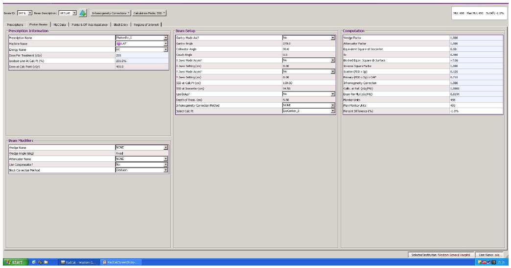
Figure 11: The saved 'Photon Beams' 'screenshot' from RadCalc for this patient. Comparing this to Figure 6, the Dose at Calc Pt (cGy) for the selected '1Rt Lat' beam has changed from '200' to '400' and, consequently, the 'IsoDose Line at calc Pt (%) entry has changed from 100% to 200%.
| A | Field | Rt Lat | Lt Lat |
| B | Contribution to prescribed dose from this field (cGy) | 1000 | 1000 |
| C | Depth dose correction | 0.826 | 0.826 |
| D | Given dose at skin (cGy) (B/C) | 1211 | 1211 |
| E | Output from Linac (cGy/mu) | 0.983 | 0.983 |
| F | Correction factor | 1 | 1 |
| G | Final output (cGy/mu) (ExF) | 0.983 | 0.983 |
| H | Total monitor units (D/G) | 1232 | 1232 |
| I | Number of fractions | 5 | 5 |
| J | Monitor units per fraction (H/I) | 246 | 246 |
Figure 12: A possible alternative layout to that in Figure 3 for the manual calculation table in the 'Radiotherapy Planning Sheet' for this patient, where the prescribed dose is divided between the two beams and entered into this table, and the labelling and ordering of the rows has been changed for greater clarity.