External wall systems in existing multi-storey residential buildings - fire risk: advice note - version 2
Version 2.0 of this Scottish Advice Note provides advice for those responsible for fire safety in residential buildings including building owners/managers/residents groups responsible for determining the fire risk posed by external wall systems on existing multi-storey residential buildings.
Part of
Annex 5: Practical Guide to the Appraisal of External Wall Systems in Residential Buildings
Background
This annex forms a guide to the practical investigation of external wall systems of residential buildings. It gives good practice principles and examples. However, appraisal specialists will need to use their experience, skills and knowledge to assess each building on an individual basis and to adapt their methodology as required. PAS 9980: 2022 Fire risk appraisal and assessment of external wall construction and cladding of existing blocks of flats may also be used to supplement this guidance. This annex can also be used as part of the Single Building Assessment (SBA) process introduced by the Scottish Government.
Annex 6 provides a simplified flowchart of the external wall system appraisal process. This may require only a desk based review and a site walkover. In other cases a full intrusive investigation will be required. Part 1 : General, of this advice note, provides guidance on criteria where an intrusive investigation may be required.
Stage 1 : Desktop Review and Site Walkover
Desktop review
Collate and review available information to understand the building construction and external wall system(s). Obtain information where it exists from the building owner, manager, original developer, system suppliers and manufacturers or local authority. See Table 5 for the types of information that may be available.
| Type of information | |
|---|---|
| Building owner, property manager and developers | Operation and maintenance manuals, the health and safety file and fire risk assessments Note: files often consist of drawings, construction records and as-built drawings, specifications, high-rise inventory entries (for buildings over 18m), manufacturers' literature (including, but not limited to, a copy of the principal construction contract, copies of contracts with any sub-contractors and, if applicable, copies of any collateral warranties), certification of products used, test reports and photographic records |
| Local authorities | Building warrant information held by the local authority, including approved warrant drawings, photographic records, amendments to warrants and completion certificates |
| Manufacturers and suppliers | Copies of material, product and system specifications, test reports, specifications and any information from third party certification of products and/or installation schemes. Design and installation advice such as fixing of cavity/fire barriers and maintenance recommendations |
Use the desk review and site walkover to identify the following:
- Building type including mixed use(s) where applicable,
- Building construction and external wall system(s),
- The vertical and horizontal lines of separation between the different uses and/or separation/compartmentation.
Use literature from the product manufacturer at the time of construction. Product manufacturers often change their products over time and the latest literature might not reflect the actual product tested or installed in the building. Clearly identify any element of the external wall system where information concerning the product could not be found.
Contact manufacturers or installers to obtain historic information about products. Analyse cladding products and materials where required.
Distinguish the divisions within the building to determine the locations of compartment or separating walls and floors. The internal layout may impact these locations, which could stagger throughout the building. This could impact the areas that might require intrusive investigation and how the building is assessed. Buildings can consist of multiple blocks or different uses and determining the separation between them will assist in assessing the risk. Figure A5.1 provides some examples of complexities that may impact on the overall appraisal.
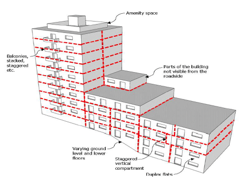
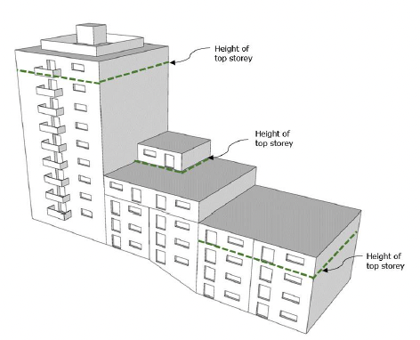
Identify the height of the overall building, including any low-rise element of the building. This can be achieved by reviewing the as-built general arrangement drawings, building warrant drawings and any specific information indicating levels. It is not uncommon for a height survey to be carried out if the building is close to any height threshold discussed in this document or if there is any doubt with the information provided by the building owner(s). Buildings can often have multiple blocks with different uses and different heights. The height survey should identify if multiple blocks are present and the various heights of the topmost storey which may have varying ground levels.
Distinguish and classify the different external wall systems and understand the interfaces between the components.
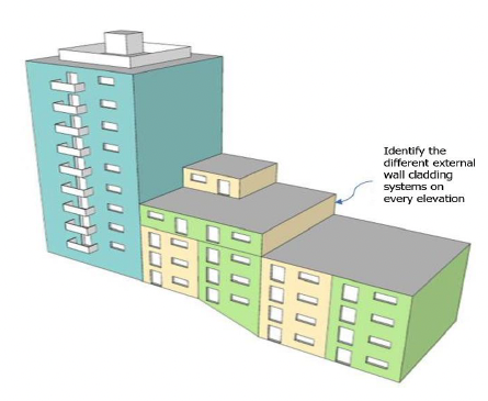
The interface between materials can often be an important consideration when establishing defects and fire risk. For example, an expanded polystyrene (EPS) insulated render wall system applied to a low rise block may interface with a rainscreen system on a taller block. The EPS insulation in this scenario might be exposed to the cavity within the rainscreen system.
Table 6 provides an example template to identify the likely fire risk of each external wall system.
| External wall construction | Layer of construction | Description | Fire Performance | Building Regulation Compliance- see Annex 3 | Relevant Manufacturer's Literature/Certification |
|---|---|---|---|---|---|
| Cladding System | Finish | ||||
| Cladding | |||||
| Insulation | |||||
| Breathable membrane | |||||
| Cavity / Fire Barriers | |||||
| Sheathing Board | |||||
| Structure (SFS / CLT / TF / Concrete etc) | |||||
| Balcony or other feature | Concrete Steel Timber Other |
Site Walkover
Carry out a site walkover to verify whether or not the desk top information reflects the actual constructed building. The appraisal specialist should consider all the evidence available and satisfy themselves that an intrusive investigation is or is not required. The building may have been altered and extended since the original construction or built differently to the drawn information. Where an intrusive investigation is required identify any limiting factors that may have an impact on the investigation.
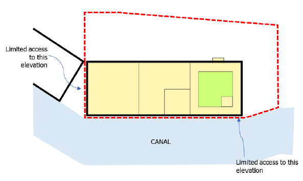
Identify boundaries of site to establish fire risk posed from adjoining buildings or other sources of ignition. Also, whether there is limited access for Scottish Fire and Rescue Service or maintenance equipment etc.
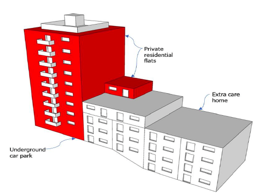
Identify multiple uses within the building. Figure A5.5 shows an example of a private residential tower consisting of flats, adjoining a low rise block consisting of extra care housing and underground car park.
Stage 2: Intrusive Site Investigation
Where it is determined that an intrusive investigation is required (see Part 1: General), the guidance in this section should be applied.
Determine the number of samples and their location in order to evidence that no defects are present. A representative sampling approach should identify a number of inspection points on each elevation and each external wall system (including any elevations at roof/terrace level). Ensure any existing warranties are not invalidated by the intrusive investigation.
Where an intrusive investigation is required, open up areas so that the sampling points can easily be repaired. Repair sample locations to maintain the fire performance, water resistance, thermal efficiency and sound resistance of the external wall. Minimise disruption from the intrusive investigation whilst ensuring that appropriate evidence confirming the construction of the external wall system is obtained.
Determine the differences across the various areas of the external wall system that require investigation to verify the overall construction. This could consist of different types of cladding, interfaces of that cladding with other parts of the building, balconies, location of cavity/fire barriers, overhangs and any other areas deemed significant by the appraisal specialist.
Determine in specific sampling areas the following:
- Cladding build up and underlying construction,
- Cavity/fire barrier locations (horizontal, vertical, edges, openings etc.),
- Interfaces between different external wall systems.
Consider samples that need to be investigated and reduce the number of openings if possible to capture more than one item in a single opening. A single sample would not be sufficient to determine that the findings observed are likely to be representative of the external wall system. The appraisal specialist will need to determine the number of samples that is required for a conclusion to be made.
Use the desktop information to identify the locations of any compartment and separating walls and floors. Horizontal and vertical compartments can be assessed by opening up the junction between the horizontal and vertical compartments.
Insulated Render Systems
For insulated render systems remove the render coat to expose cavity/fire barriers, insulation, fixings and background structure. The area opened up should expose the insulation either side of the cavity/fire barrier. An insulated render system can vary greatly in its construction from manufacturer to manufacturer including the design of cavity/fire barriers.
Figure A5.6: Removal of thin coat render to expose vertical and horizontal compartments
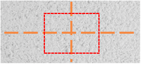
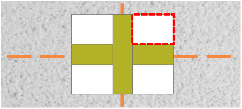
Check the position of the cavity/fire barriers to determine whether or not the barriers are in line with the compartment or separating walls and floors and whether or not the barriers are correctly installed. This can be carried out by removing the insulation on either side of the barrier and possibly the sheathing boards to expose the edge of the vertical compartment or separating wall or edge of the horizontal compartment or separating floor. The removal of the insulation either side will provide a cross section of the barriers for the interface to be examined.
Figure A5.7: Removal of insulation at mineral wool fire barrier
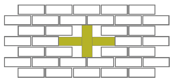
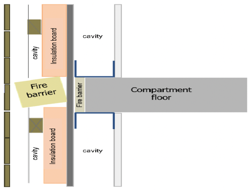
Brickwork / masonry cladding
Similarly, where the removal of brickwork or masonry cladding is necessary, this should be carried out on the lines of separating or compartment walls and floors as shown in figure A5.8 and A5.9.
Figure A5.8: Extent of the brickwork / masonry removed on line of compartment or separating walls and floors
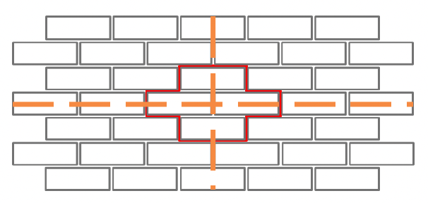
Figure A5.9: Expose the entire width of vertical and horizontal cavity/fire barriers
Rainscreen Cladding
For rainscreen cladding remove the outer cladding boards to inspect for the following:
- The condition of the components of the rainscreen cladding system,
- Confirm the identity of the cladding material, including marking and labelling, layers in composite materials and other features,
- The presence and type of insulation exposed in the cavity,
- The adequacy of cavity/fire barriers,
- The condition and adequacy of the support and fixing materials.
The removal of a single board may not be sufficient and the opening should be large enough to uncover the location of the compartment or separating walls and floors.
Sample Testing
Test materials from site only where they cannot be identified or there is limited information concerning their fire performance. There is no need to test materials if there is sufficient reliable data that can be verified on the fire performance of the cladding and insulation materials.
Photographs
Photograph the construction of the external wall system and if any defects that may have been identified during the site walkover and intrusive investigation.
Consider the following when taking photographs during an intrusive investigation:
- Photograph the entire sample location prior to opening up and then after opening up,
- Take detailed photographs straight onto the opening and not at an angle,
- Capture the different layers of construction and the fixings, including the thicknesses,
- Annotate the photographs with clear reference to the date on which they were taken and the location within the building. Include:
- Fixing type, depth, gauge and centre spacing,
- Thicknesses of materials and a description of the material observed,
- Markings, labels or other identifiable markings,
- Cavity depths,
- Photograph any defects e.g. deformed insulation boards, lack of fixings, discontinuous cavity/fire barriers, erosions and degradation.
Take measurement of materials (metric units – mm or m) perpendicular to the materials being measured. The measure (ruler and tape) must be perpendicular to the surface (90 degrees from flat surface). Hold firmly against the surface of the component being measured without deflecting the surface.
Take photographs perpendicular to the measure to avoid any parallax error.
Stage 3: Analysis and Conclusion
Analyse all evidence gathered from the desk based review, site walkover and intrusive investigation if carried out.
Part 2 : Technical of this advice note focuses on the process of determining fire risk. Sections 2.1 and 2.2 establish benchmarks to assist in the determination of risk and provide relevant background information. Sections 2.3 and 2.4 provide risk-based guidance on cladding systems. The following figures supplement this guidance and show typical construction defects that may be encountered following a desk based review and / or intrusive investigation.
In order to simplify the decision making process, Section 2.5 provides two categories of risk. Those buildings that require remediation are categorised as 'High Risk' and buildings where no remediation is required are categorised as 'Low Risk'. Where the appraisal specialist is unsure of the risk rating outcome, further investigation should be carried. This may include gathering more documentation / evidence, an intrusive investigation and/or testing of materials or systems to establish the final risk rating outcome. Any action plan produced to mitigate and remediate 'High Risk' external wall systems should provide timeframes taking account of the holistic fire risk assessment and be proportionate to the risk to life.
Figure A5.10 shows that the cavity behind the mineral wool barrier was not closed and this EWI system required an intumescent strip to be installed behind the gypsum based board to complete the manufacturer's detail.
Figure A5.10: Section through separating floor in an External Wall Insulation (EWI) system
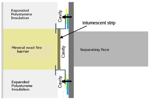
Figure A5.11 shows missing cavity/fire barriers at the junction detail between the separating wall and external wall construction. The Steel Framing System (SFS) is often installed to project over the concrete structure by up to 12mm. The offset of the SFS, often leaves a cavity at the edge of the concrete structure and cavities behind the sheathing board are not filled.
Figure A5.11: Compartment wall interface with terracotta cladding (plan view)
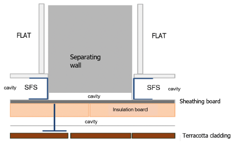
Figure A5.12 shows an intumescent faced fire barrier misaligned with the separating wall.
Figure A5.12: Cavity barrier mis-aligned behind timber cladding (plan view)
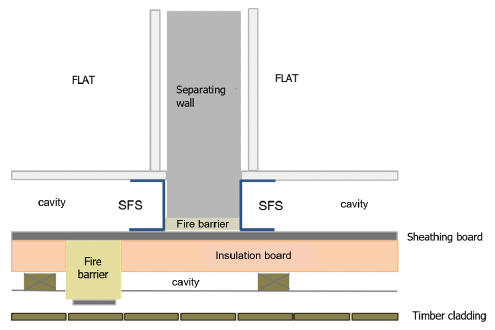
Figure A5.13 shows a steel framed structure with fire-stopping between the edge of the compartment floor and sheathing board. The cladding structure is interrupting the vertical fire barrier causing gaps to open up between vertical and horizontal fire barriers.
Figure A5.13: Horizontal and vertical fire barrier junction in a timber cladding system (sectional view)
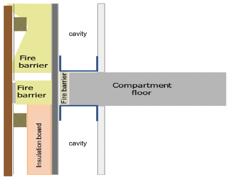
Figure A5.14 shows a steel framed structure (SFS), fire-stopping at the edge of the compartment floor with a fire barrier which is incorrectly installed.
Figure A5.14: Section through compartment floor junction with timber cladding system
Stage 4: Reporting
Report all activities undertaken in the external wall appraisal, information obtained, conclusions and recommendations. A contents list is given in Table 7 for appraisers to use as a guide. Use this guidance to undertake the appraisal and provide explanation in the discussion section. Clearly set out the findings in the executive summary and the conclusions.
| Contents / Main Headings | Description |
|---|---|
| Executive Summary | Summarise the detailed findings, conclusions and recommendations so that readers can determine the issues found with the building prior to reading the detail Ensure that the risk rating, high or low, is clearly set out Briefly state any remedial works if required |
| Introduction | Provide an introduction which outlines their instruction, contributors to the report and site visit dates. The external wall appraiser should also describe their qualifications, experience and suitability to carry out an external wall appraisal |
| Building and Cladding Description | Report the building use (including mixed use), building height and ground levels, number of flats (where applicable), fire strategy, number of escape stairs and equipment to assist fire-fighting etc. Include diagrams and drawings that describe the building and cladding systems Include a description of the information relied on to determine the date of the relevant building regulations applicable to the building |
| Desktop Review | Describe the construction of each cladding system observed on the building Use general arrangement drawings to show the compartment and / or separating walls and floors Extract details from drawings to demonstrate the different external wall build ups on the building Report the information contained within trade literature, certification, test reports, etc |
| Site Walkover | Include photographs of the buildings' elevation from the site walkover Describe all findings including any non-fire related defects that may impact on fire performance of the external wall system e.g. signs of water ingress requiring further intrusive investigation. Report the use made of the information gathered to plan the intrusive investigation where this is required |
| Intrusive Investigation, where undertaken | Address any defects discovered Describe each cladding type in detail Identify sampling locations using diagrams Establish a logical numbering system and cross reference with schedule and elevation mark ups which will assist with identifying where the photographs of the inspection areas were taken Use a summary table of the findings to provide an overview of the different external wall build ups and fire performance (see Table 6 ) |
| Risk assessment and discussion | Analyse the findings following the desktop review and site investigation, including any results from the testing of materials Carry out the risk assessment to determine whether the cladding system is high or low risk and record the reasons for the rating Include supporting information from other consultants assisting with the overall determination of risk |
| Analysis and Conclusion | Present a clear set of conclusions, including the risk rating, and the degree of compliance with legislation or best practice guidance. Identify the extent of any defects and provide an outline mitigation and /or remediation strategy for the design consultants to develop a detailed solution |
| Appraisers declaration | Include a declaration covering as a minimum: authorisations, qualifications, experience, skills and knowledge to carry out the external wall appraisal as described in this document Confirm that all consultants assisting with the review, investigation and determination of the external wall appraisal have the necessary authorisation, qualifications, experience, skills and knowledge to carry out the task assigned to them Provide evidence that all consultants/ sub-consultants have adequate professional indemnity insurance to carry out the external wall appraisal and to advise on a remediation strategy Confirm that the investigation, conclusion and recommendations are impartial and independent |
| Appendices | Use appendices to report detailed information such as information on products, drawings, specifications, site investigation photographs, results of testing (where undertaken) |
Contact
Email: BuildingStandards@gov.scot