Marine piling - energy conversion factors in underwater radiated sound: review
A report which investigates the Energy Conversion Factor (ECF) method and provides recommendations regarding the modelling approaches for impact piling as used in environmental impact assessments (EIA) in Scottish Waters.
This document is part of a collection
Appendix A. Pile Driving Source Model
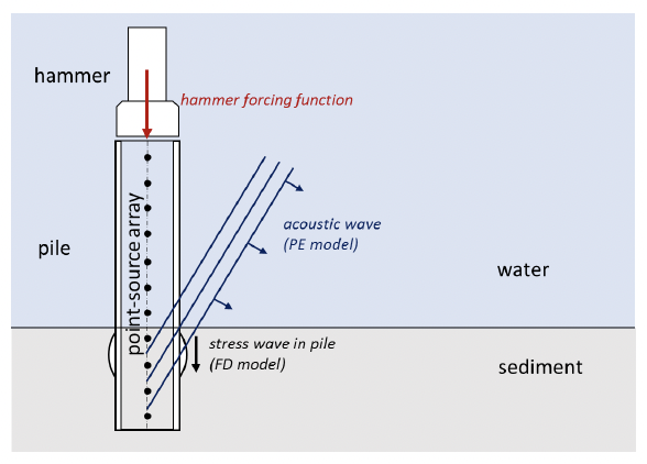
A physical model of pile vibration and near-field sound radiation is used to calculate the radiated sound from impact piling. The physical model employed in this study computes the underwater vibration and sound radiation of a pile by solving the theoretical equations of motion for axial and radial vibrations of a cylindrical shell. These equations of motion are solved subject to boundary conditions, which describe the forcing function of the hammer at the top of the pile and the soil resistance at the base of the pile (Figure A‑1). Damping of the pile vibration due to radiation loading is computed for Mach waves emanating from the pile wall. The equations of motion are discretised using the finite difference (FD) method and are solved on a discrete time and depth mesh.
To model the sound emissions from the piles, the force of the pile driving hammers also had to be modelled. The force at the top of each pile was computed using the GRLWEAP 2010 wave equation model (GRLWEAP, Pile Dynamics 2010), which includes a large database of simulated hammers—both impact and vibratory—based on the manufacturers’ specifications. The forcing functions from GRLWEAP were used as inputs to the FD model to compute the resulting pile vibrations.
The sound radiating from the pile itself is simulated using a vertical array of discrete point sources. The point sources are centred on the pile axis. Their amplitudes are derived using an inverse technique, such that their collective particle velocity, calculated using a near-field wave-number integration model, matches the particle velocity in the water at the pile wall. The sound field propagating away from the vertical source array is then calculated using a time-domain acoustic propagation model (i.e., RAM). MacGillivray (2014) describes the theory behind the physical model in more detail.
Contact
Email: ScotMER@gov.scot
There is a problem
Thanks for your feedback