4.9 Danger from heat
|
Guidance is given under this standard on a number of issues relating to hot water safety.
Guidance is given to minimise the risk of explosion due to malfunction of an unvented hot water vessel by:
ensuring that such installations are carried out by appropriately qualified personnel, and
requiring a minimum range of safety devices be fitted to any such installation to prevent the temperature of the stored water exceeding 100°C.
It is not intended that this guidance should be applied to storage systems with a capacity of less than 15 litres, to systems used solely for space heating or to any system used for an industrial or commercial process.
Hot water overflows - guidance is given on provisions for the safe removal of the discharge created by the normal operation of safety devices in such an installation to a safe and visible location.
Sanitary facilities - measures to prevent scalding from hot water are now addressed for certain sanitary facilities used for personal hygiene. Provisions and specific temperature limits, additional to recommendations in this guidance, may be applicable to certain building types or uses under other legislation, particularly through duties under Health and Safety legislation.
Maintaining safety devices - safety devices installed to protect from hazards such as scalding or the risk of explosion of unvented systems should be maintained to ensure correct operation. This forms part of an operator’s duty of care under Health and Safety legislation. Guidance on maintenance can be provided by both manufacturers and installers of such devices.
Conversions - in the case of conversions, as specified in regulation 4, the building as converted shall meet the requirement of this standard (regulation 12, schedule 6).
Installation of an unvented hot water storage system should be carried out by a person with appropriate training and practical experience.
Competence of installers - this might include current membership of a registration scheme operated by a recognised professional body. This could include those administered by the Scottish and Northern Ireland Plumbing Employers Federation (SNIPEF) and the Construction Industry Training Board (CITB) or an equivalent body.
The following points should be noted in relation to installation of an unvented hot water storage system:
the installer should be a competent person and, on completion, the labelling of the installation should identify the installer
the installed system should meet the recommendations of BS 7206: 1990 or be the subject of an approval by a notified body and incorporate the safety devices outlined in clause 4.9.2
certification of the unit or package should be recorded by permanent marking and a warning label which should be visible after installation. A comprehensive installation/user manual should be supplied
the tundish and discharge pipework should be correctly located and fitted by the installer and the final discharge point should be visible and safely positioned where there is no risk from hot water discharge.
The operation of the system under discharge conditions should be tested to ensure provision is adequate.
An unvented hot water storage system should be designed and installed to prevent the temperature of the stored water at any time exceeding 100ºC and to provide protection from malfunctions of the system.
An unvented hot water storage system should be in the form of a proprietary unit or package which is in accordance with the recommendations of a relevant standard such as BS 12897: 2006, BS 6700: 2009 as appropriate or the subject of approval by a notified body to an equivalent level of safety and performance.
Pressure controls for a unit or package could include:
a check valve to prevent backflow, and
a pressure control valve to suit the operating pressure of the system, and
an expansion valve to relieve excess pressure, and
an external expansion vessel or other means of accommodating expanded heated water.
These devices are generally factory-fitted (unit) or supplied for fitting by the installer (package).
Independent safety devices - unit or package should have a minimum of 2 independent safety devices. An acceptable approach could be:
a non self-resetting thermal cut-out, and
a temperature relief valve or pressure relief valve (or combined temperature pressure relief valves).
These devices should be in additional to any thermostatic control that is fitted to maintain the temperature of the stored water at around 60ºC.
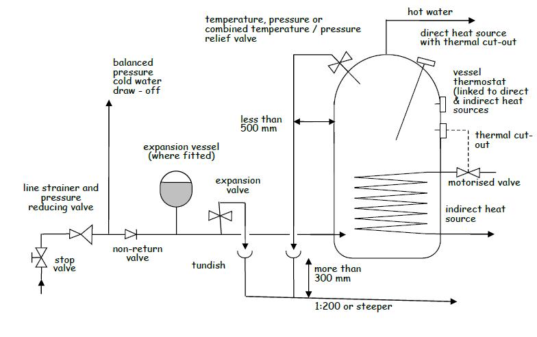
Thermal cut-out - a temperature-operated, non self-resetting, energy cut-out should be fitted to the vessel. In the event of thermostat failure, heating to the water in the vessel should stop before the temperature rises to the critical level required for operation of the temperature relief valve.
In indirectly heated vessels, the non self-resetting thermal cut-out should operate a motorised valve, or other similar device, to shut off the flow from the heat source.
On directly heated vessels or where an indirectly heated vessel has an alternative direct method of water heating fitted, a non self-resetting thermal cut-out device should be provided for each direct source.
The safety relief valve should be located directly on the storage vessel. The relief valve should conform to the relevant national standards such as BS 6283 Part 2: 1991 for temperature relief valves or BS EN 1490: 2000 for combined temperature and pressure relief valves which are set to open at temperatures not normally exceeding 90ºC.
The relief valve should have a discharge capacity rating at least equal to the rate of energy (power in kilowatts) input to the heat source. In the case of an indirectly heated unit or package, the valve should be tested to discharge water at a rate not less than 500kg/h for systems up to 45kW. The discharge pipework should accommodate this flow rate.
An unvented hot water storage system should be designed and installed to prevent the temperature of the stored water at any time exceeding 100ºC and to provide protection from malfunctions of the system.
Installations of this size will generally be specified to individual designs rather than supplied as proprietary units. The provision of evidence of compliance with safety requirements equivalent to the level set out in clause 4.9.2 should be the responsibility of the designer of the system.
Where the system has a power input of less than 45kW, safety devices should be provided in accordance with the recommendations of a relevant standard such as BS EN 12897:2006 or BS 6700:2009 as appropriate.
Where the system has a power input greater than 45kW, safety devices should include an appropriate number of temperature or combined temperature/pressure relief valves:
to BS 6283: Part 2: 1991 or BS EN 1490: 2000, or
of equivalent suitability marked with the activation temperature (in ºC), pressure (if relevant) and the discharge rating (in kW), measured in accordance with Appendix F of BS 6283 Part 2: 1991 or BS EN 1490: 2000.
Relief valves should provide a combined discharge rating at least equal to the power input of the system.
Provision of thermal cut-outs appropriate to the installation heat source(s) should be provided as noted in clause 4.9.2.
Discharge pipework should be provided as noted in clause 4.9.4, noting that the size of piping should be designed to accommodate the required discharge capacity and may exceed the guidance given in the table to clause 4.9.4.
The removal of discharges of water from the system can be considered in three parts.
Relief valve to tundish - each valve should discharge into a metal pipe not less than the nominal outlet size of the valve. The discharge pipe should have an air-break, such as a tundish, not more than 500mm from the vessel relief valve and located in an easily visible location within the same enclosure. Discharge pipes from more than one relief valve may be taken through the same tundish.
Pipework should be installed so that any discharge will be directed away from electrical components should the discharge outlet become blocked.
Tundish to final discharge point - the presence of this air break results in the pressure of the final discharge being no higher than that of a vented system.
The discharge pipe from the tundish to final discharge point should be of a material, usually copper, capable of withstanding water temperatures of up to 95ºC and be at least one pipe size larger than the outlet pipe to the relief valve.
A vertical section of pipe, at least 300mm long, should be provided beneath the tundish before any bends to the discharge pipe; thereafter the pipe should be appropriately supported to maintain a continuous fall of at least 1 in 200 to the discharge point.
The pipework should have a resistance to the flow of water no greater than that of a straight pipe 9m long unless the pipe bore is increased accordingly. Guidance on sizing of pipework from the tundish to the final discharge point is shown in the following table:
Table 4.6. Size of discharge pipework
| Valve outlet size | Minimum size of discharge pipe to tundish | Minimum size of discharge pipe from tundish | Maximum resistance allowed, expressed as a length of straight pipe i.e. no elbows or bends | Equivalent resistance created by the addition of each elbow or bend |
|---|---|---|---|---|
| G ½ | 15mm | 22mm 28mm 35mm |
Up to 9m Up to 18m Up to 27m |
0.8m 1.0m 1.4m |
| G ¾ | 22mm | 28mm 35mm 42mm |
Up to 9m Up to 18m Up to 27m |
1.0m 1.4m 1.7m |
| G 1 | 28mm | 35mm 42mm 54mm |
Up to 9m Up to 18m Up to 27m |
1.4m 1.7m 2.3m |
Annex D to BS 6700: 1997 "Specification for design, installation, testing and maintenance of services supplying water for domestic use within buildings and their curtilages” also gives guidance on pipe sizing for water distribution systems.
Discharge pipe termination
The pipe termination should be in a visible location and installed so that discharge will not endanger anyone inside or outside the building.
Ideally, the final discharge point should be above the water seal to an external gully and below a fixed grating. Other methods for terminating the final discharge point would include:
up to 100mm above external surfaces such as car parks, grassed areas, or hard standings; a wire cage or similar guard should be provided to both prevent contact with discharge and protect the outlet from damage, whilst maintaining visibility
at high level into a hopper and downpipe of a material, such as cast iron, appropriate for a hot water discharge with the end of the discharge pipe clearly visible
onto a flat roof or pitched roof clad in a material capable of withstanding high temperature discharges of water, such as slate/clay/concrete tiles or metal sheet, with the discharge point a minimum of 3m from any plastic guttering system that would collect such discharges.
Discharge at high level may be possible if the discharge outlet is terminated in such a way as to direct the flow of water against the external face of a wall. However evidence of the minimum height of the outlet above any surface to which people have access and the distance needed to reduce the discharge to a non-scalding level should be established by test or otherwise.
Guidance to the Water Byelaws recommends that, to prevent the development of Legionella or similar pathogens, hot water within a storage vessel should be stored at a temperature of not less than 60ºC and distributed at a temperature of not less than 55ºC. Detailed guidance on the control of Legionella may be found in HSE Approved Code of Practice L8 – ‘Legionnaires’ Disease – Control of Legionella Bacteria in Water Systems’.
If water is supplied at high temperature from any source, there is a danger of scalding to building users. Risk of severe injury increases proportionally with increase in temperature and with extent of contact.
Facilities used for personal hygiene - to prevent scalding, the temperature of hot water, at point of delivery to a bath, shower or bidet, should be limited.
A device or system limiting water temperature should not compromise the principal means of providing protection from the risk of Legionella. It should allow flexibility in setting of a delivery temperature, up to a maximum of 48ºC, in a form that is not easily altered by building users.
Delivery temperature of hot water to a facility should relate to the vulnerability of people who may use the facility, particularly elderly people or unsupervised children, who are more at risk from injury. Reference should be made to existing recommendations on duty of care and risk assessment made under Health and Safety legislation and, in addition, to the following guidance available for specific building types:
for residential care buildings, to recommendations in HSE publication HSG220 - ‘Health & Safety in Care Homes’
for healthcare buildings, to recommendations in NHS Scotland Scottish Health Guidance Note ‘Safe Hot Water and Surface Temperatures’
for schools, public buildings and buildings open to the public, to recommendations in 'Guidance to the Water Byelaws’, issued by Defra.
Where both hot and cold water are supplied to a facility, the above may be achieved, for single or limited outlet applications, by use of a thermostatic mixing valve (TMV) or fitting complying with BS EN 1111: 1999 or BS EN 1287: 1999, fitted as close to the point of delivery as practicable. Guidance on the installation, use and maintenance of thermostatic mixing valves and fittings for domestic-scale applications may be found in BRE information Paper IP 14/03 or from the Thermostatic Mixing Valve Association (TMVA).