Annex 6.B Compensatory approach - heat loss example
This annex gives an example of the compensatory approach for use in the design of conversions, extensions and alterations. This is likely to be of use where there is a need to specify one or more constructions with a U-value higher than the recommended maximum area-weighted average U-values given in either column (a) or (b) of the table to clause 6.2.9.
The examples given in this instance are for an attic conversion and for a single storey extension, however the same principles apply to other substantial alterations, extensions and conversions:
example 6.B.1 shows use of better U-values to some elements to compensate for lack of headroom in an attic conversion where column (b) U-values apply
example 6.B.2 shows use of better U-values to enable a larger area of glazing within an extension where column (b) U-values apply
example 6.B.3, based on the extension shown in 6.B.2, shows a building where column (a) area-weighted U-values apply and target the heat loss limit being met by a combination of an extension which meets or exceeds column (b) U-values and fabric improvements to the existing building.
Note that this method can only be used in conversions, if the recommended U-values are met in full, not where values are being met as far as is reasonably practicable.
Separate work under the same building warrant - a single compensatory approach calculation can be carried out to cover separate areas of work to an existing dwelling provided the same assessment criteria (maximum U-values, etc) are applicable to each area of work.
Note: where works are a conversion, works are subject to the U-values within column (b) in the table to clause 6.2.9.
It is proposed to form two rooms in the roof space of an existing single storey dwelling. The extra floor area created (including opening for stairway) will be 36.4m2. A plan and section of the proposed layout is shown in the figure below. A key part of the design is to create as much headroom as possible below the new coombe ceilings. The existing rafters are only 150mm deep therefore it is difficult to achieve the recommended elemental U-value of 0.18 (see column (b) in the table to clause 6.2.9), without using branders or having an excessive thickness of insulated ceiling lining. The principal compensatory measure will be to highly insulate the attic walls that occur directly below the lowest part of the coombes. The existing gables will be provided with insulated internal wall lining to improve the U-value where the insulation envelope now occurs. The four no. 1.5m2 rooflights installed have timber frames. The floor that will be formed at the line of the existing ceiling ties is wholly within the insulation envelope and is therefore disregarded for the purposes of this calculation.
Procedure:
The heat loss for a ‘notional attic’ (i.e. an attic the same size and shape as the proposed attic but with its area of window/doors/ rooflights taken as a maximum 25% of the floor area) is calculated using the U-values in column (b) in the table to clause 6.2.9.
The internal exposed surface areas of each of the elements of the proposed building insulation envelope that have different area weighted U-values are calculated.
The heat loss for the proposed attic is calculated using proposed U-values for building elements, which may be higher or lower than those recommended in column (b) of the table to clause 6.2.9. The percentage area of windows/doors/rooflight area as proposed may also be greater or less than 25%.
Finally, the heat loss calculated for the proposed attic should be less than or equal to that for the 'notional' one.
Calculate the rate of heat loss from the 'notional attic' as follows:
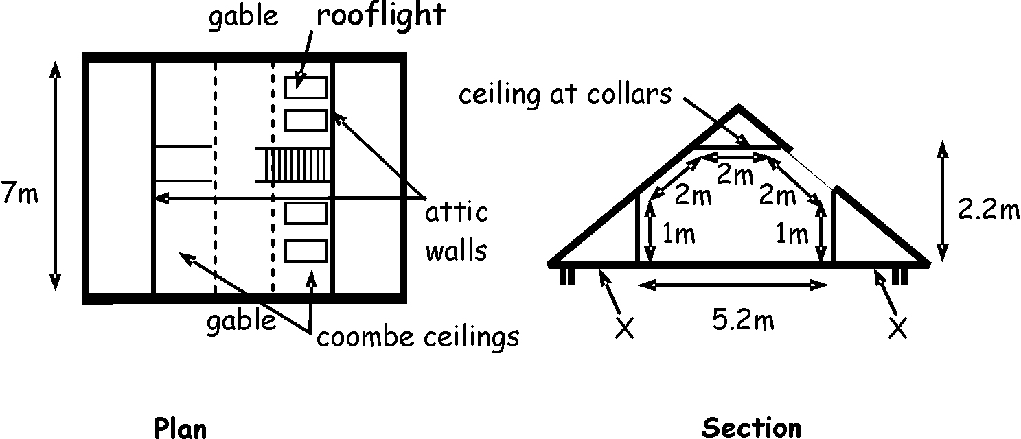
Table 6.7. Data for 'notional' attic alteration
| Exposed element | Exposed surface area (m2) | Column (b) U-value (W/m2K) | Rate of heat loss (W/K) | ||
|---|---|---|---|---|---|
| Gables | 19.0 | x | 0.22 | = | 4.18 |
| Attic walls | 14.0 | x | 0.22 | = | 3.08 |
| Ceiling at collars | 14.0 | x | 0.15 | = | 2.10 |
| Coombe ceiling | 18.9 | x | 0.18 | = | 3.40 |
| Rooflights | 9.1 (25%) | x | 1.6 | = | 14.56 |
| Total rate of heat loss | = | 27.32 | |||
Then calculate the rate of heat loss from the proposed attic as follows:
Table 6.8. Data for proposed attic alteration
| Exposed element | Exposed surface area (m2) | Column (b) U-value (W/m2K) | Rate of heat loss (W/K) | ||
|---|---|---|---|---|---|
| Gables | 19.0 | x | 0.30 | = | 5.70 |
| Attic walls | 14.0 | x | 0.20 | = | 2.80 |
| Ceiling at collars | 14.0 | x | 0.15 | = | 2.10 |
| Coombe ceiling | 22.0 | x | 0.32 | = | 7.04 |
| Rooflights | 6.0 (16.5%) | x | 1.6 | = | 9.60 |
| Total rate of heat loss | = | 27.24 | |||
From the above comparison, the rate of heat loss from the proposed attic (27.24) is less than that from the 'notional attic' (27.32). Proposals will comply.
Additional insulation work - the existing dwelling is of an age where there was no insulation provided in the roof space at the time of the original construction. Guidance on ‘reconstruction of elements’ within clause 6.2.11 recommends that where an element forming part of the insulation envelope is to be altered or dismantled and rebuilt, the opportunity should be taken to improve the level of thermal insulation.
In this example, there is no technical risk or other reason which prevents the level ceiling at the eaves of the roof (see X on the section) being upgraded to achieve a U-value of 0.15 as noted in column (b) of the table to clause 6.2.9. This would therefore be required as part of the proposed works.
Note: in this example, the fabric performance of the existing building allows use of the U-values within column (b) in the table to clause 6.2.9.
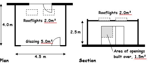
It is proposed to form a single room, flat-roof extension to the rear of an existing dwelling. The floor area of the extension is 18.0m2 and it is to be built over existing openings totalling 1.5m2 in area. A plan and section of the proposed layout is shown in the figure below. A key element of the design is provision of significant glazing (5.0m2) to the end wall of the extension to provide views across the large garden and rooflights (2.0m2) to maximise light into the existing dwelling. However, this area of openings is in excess of the maximum recommended in clause 6.2.9, 25% of the extension floor area plus any built-over openings. To achieve compliance with Standard 6.2, it is proposed to increase insulation U-values in floor and roof.
Procedure:
The heat loss for a ‘notional extension’ (i.e. one the same size and shape as the proposed extension but with the area of window/doors/rooflights taken as a maximum 25% of the floor area plus the area of any built-over openings) is calculated using the U-values in column (b) in the table to clause 6.2.9. As no differentiation is made between U-values for doors, windows and for rooflights, the applicant may determine from which element(s) of the envelope this area is deducted.
The internal exposed surface areas of each of the elements of the proposed building insulation envelope that have different area-weighted U-values are calculated.
The heat loss for the proposed extension is calculated using proposed U-values forbuilding elements, which may be higher or lower than those recommended in column (b) of the table to clause 6.2.9. The percentage area of windows/doors/rooflight area, as proposed, may also be greater or less than 25%.
The total area of exposed elements will not be the same for notional and proposed extensions where there is any area of built-over openings, which are added only to the notional extension.
Finally, the heat loss for the proposed extension should be less than or equal to that for the 'notional' one.
Calculate the rate of heat loss from the ‘notional’ extension as follows:
Table 6.9. 'Data for 'notional extension'
| Exposed element | Exposed surface area (m2) | Design U-values (W/m2K) | Rate of heat loss (W/K) | ||
|---|---|---|---|---|---|
| Floor | 18.0 | x | 0.18 | = | 3.24 |
| Roof | 18.0 | x | 0.18 | = | 3.24 |
| External wall | 26.8 | x | 0.22 | = | 5.89 |
| Openings | 4.5 (25%) + 1.5 (built over) | x | 1.6 | = | 9.6 |
| Total rate of heat loss | = | 21.97 | |||
Then calculate the rate of heat loss from the proposed extension as follows:
Table 6.10. Data for proposed extension
| Exposed element | Exposed surface area (m2) | Column (b) Design U-values (W/m2K) | Rate of heat loss (W/K) | ||
|---|---|---|---|---|---|
| Floor | 18.0 | x | 0.15 | = | 2.70 |
| Roof | 16.0 | x | 0.15 | = | 2.40 |
| External wall | 26.3 | x | 0.22 | = | 5.79 |
| Openings | 5.0 + 2.0 | x | 1.4 | = | 9.80 |
| Total rate of heat loss | = | 20.69 | |||
From the above comparison, the rate of heat loss from the proposed extension (20.69) is less than that from the 'notional extension' (21.97). Proposals will comply.
Using the example above, this further exercise shows how an applicant may, where column (a) U-values apply, demonstrate compliance where an extension has an overall heat loss better than that for a column (b) notional extension, with the balance of energy savings delivered through improvement to the fabric of the existing dwelling.
The first additional step is calculating the total rate of heat loss for the more challenging column (a) notional extension, using the same process outlined in clause 6.B.2.
Table 6.11. Data for column (a) 'notional extension'
| Exposed element | Exposed surface area (m2) | Column (a) Design U-values (W/m2K) | Rate of heat loss (W/K) | ||
|---|---|---|---|---|---|
| Floor | 18.0 | x | 0.15 | = | 2.70 |
| Roof | 18.0 | x | 0.13 | = | 2.34 |
| External wall | 26.8 | x | 0.17 | = | 4.56 |
| Openings | 4.5 (25% + 1.5 (built over) | x | 1.4 | = | 8.40 |
| Total rate of heat loss | = | 18.0 | |||
The exercise in clause 6.B.2 identified a proposed extension which met or improved upon the heat loss for a column (b) notional extension, as follows:
Table 6.12. Data for proposed extension
| Exposed element | Exposed surface area (m2) | Column (a) Design U-values (W/m2K) | Rate of heat loss (W/K) | ||
|---|---|---|---|---|---|
| Floor | 18.0 | x | 0.15 | = | 2.70 |
| Roof | 16.0 | x | 0.15 | = | 2.40 |
| External wall | 26.3 | x | 0.22 | = | 5.79 |
| Openings | 5.0 + 2.0 | x | 1.4 | = | 9.80 |
| Total rate of heat loss | = | 20.69 | |||
This allows the difference in rate of heat loss between the column (a) notional extension and the column (b) proposed extension to be identified.
Rate of heat loss to be addressed: 20.69 – 18.0 = 2.69 W/K
In this example, to deliver this improvement within the existing dwelling, additional insulation of an accessible roof space is proposed.
Roof space of 20m2 with 150mm mineral wool insulation between ties. Top up of 150mm insulation, laid at right angles to roof ties.
Table 6.13. Benefit of proposed improvement measure(s)
| Benefit of proposed improvement measure(s) | |
|---|---|
| U-value of existing construction | 0.29W/m2/K |
| U-value of proposed construction | 0.14W/m2/K |
| Reduced rate of heat loss per m2 of insulation | 0.15W/K |
| Area applicable to proposed measure | 20m2 |
| Total reduction in heat loss for proposed measure |
3.0W/K |
Note: Benefit of improvement measure should be supported by full material specification and U-value calculation.
Total rate of heat loss (proposed extension – improvement measures) should not exceed total rate of heat loss (column (a) notional extension).
In this case: 20.69 – 3.0 = 17.69.
From the above comparison, the rate of heat loss from the proposed extension and improvements (17.69) is no more than that from the column (a) 'notional extension' (18.0).
The rate of heat loss from the proposed extension is also no more than for a column (b) notional extension. Proposal will therefore comply.