2.9 Escape
|
While the number of deaths from fires in non-domestic buildings is less than domestic buildings the potential for significant life loss and injuries is far greater. This is due to the large occupancy capacities that may be involved and the complexity of occupant behaviour including the potential for delay in occupant evacuation following the outbreak of fire.
Occupants in buildings do not normally perceive themselves to be at risk from fire and are not fully aware of the speed that fire can spread. The risk to occupants is greater if they are asleep during the outbreak of fire as their ability to detect a fire and to escape will be greatly impaired.
Everyone within a building should be provided with at least one means of escape from fire that offers a safe passage to a place of safety outside the building. This should allow for them to escape from the building before being affected by fire or smoke. In certain circumstances, for example, where the travel distance is excessive, a second means of escape should be provided. This will allow the occupants to turn away from the fire and make their escape in the other direction. There may be up to four stages in the process of escape:
-
escape from the room of fire origin or escape from the fire where only one direction is possible
-
escape from the compartment of fire origin or until the safety of a fire resisting wall is reached
-
escape from the floor of fire origin to protected zones and escape stairs, and
-
escape from the building to a place of safety at ground level.
Due to the special fire precautions within residential care buildings, hospitals and enclosed shopping centres, additional guidance is provided in the annexes. However it is important to remember that the guidance in the annexes is in addition and supplementary to the guidance to Standard 2.1 to 2.15. For additional guidance on:
-
residential care buildings, see annex 2.A
-
hospitals, see annex 2.B
-
enclosed shopping centres, see annex 2.C.
Conversions - in the case of conversions, as specified in regulation 4, the building as converted shall meet the requirement of this standard (regulation 12, schedule 6).
The occupants should be able to leave the building or part of the building in relative safety during the outbreak of a fire without assistance from the fire and rescue service.
Designers generally achieve this by providing independent routes of escape either directly to a place of safety, or through an adjacent compartment or protected zone.
The time available to leave a room or compartment of fire origin before being overcome by fire or smoke is dependant on a number of key factors:
-
the number and mobility of occupants in the compartment or room of fire origin
-
the containment measures of the room or compartment of fire origin
-
the geometry of the room or compartment
-
means of early warning of fire
-
the fire dynamics (e.g. the fire load and the rate of fire growth)
-
the distance to reach a place of safety, a protected zone or another compartment, and
-
the number and width of exits.
There are many options available to designers when considering escape from buildings to a place of safety. However these options can be subdivided into 3 broad categories:
-
direct escape
-
internal escape
-
external escape.
Direct escape means that occupants can escape from a building directly to a place of safety by way of a final exit door without using an internal or external escape route. Whilst direct escape to a place of safety is preferable, this is not always possible or convenient, for example, in hospitals or multi-storey buildings with many floors high above the ground.
Internal escape is perhaps the most common method of escape from buildings. Occupants escape from fire using enclosed corridors and stairs inside the building to reach a final exit door from the building, which leads to a place of safety.
External escape routes are wholly or partially open to the external air therefore the risk of smoke logging is reduced compared with enclosed escape routes inside the building. External escape routes include external escape stairs, access decks and flat roofs. In certain circumstances, an escape route from a building may be by way of a flat roof or an access deck.
The use of a building and its occupancy capacity can vary considerably. It is necessary therefore to calculate the appropriate number of occupants in each space for normal circumstances.
The occupancy capacity can be estimated by assigning a floor area per occupant, this is called the occupancy load factor. The occupancy capacity of a room or space (without fixed seating) can then be obtained by dividing the area in square metres by the relevant occupancy load factor. While some buildings such as residential buildings are designed for a definitive number of occupants other occupancies such as in offices can vary.
The table below is based on the following characteristics of the occupancy:
-
assembly and entertainment buildings, which may have high occupancy density and large undivided floor areas
-
offices, where desks, cabinets and office machinery will be present
-
shops, where display shelves, counters and racks will be present
-
residential buildings, where the number of occupants is generally controlled by the number of beds available
-
factory and storage buildings, where the occupancy capacity is normally low and goods or machinery will be present.
The values in the table can be used as a guide to assess the occupancy capacity of a room. Where the occupancy load factors listed in the table below are not used, a written statement of the occupancy capacity should be submitted to the verifier who may wish to confirm the figures (e.g. occupancy capacity may be based on the number of available seats; the figure should include the number of spaces available for wheelchair users).
Table 2.10. Occupancy capacity in rooms and spaces without fixed seating
| Description of room or space | Occupancy load factor |
|---|---|
| Standing spectators’ area | 0.3 |
| Amusement arcade, assembly hall (including a general-purpose place of assembly), bar (public area), bingo hall | 0.5 |
| Concourse, dance floor, queuing area | 0.7 |
| Committee room, common room, conference room, dining room, licensed betting office (public area), lounge (other than a lounge bar), meeting room, reading room, restaurant, staff room, waiting room | 1.0 |
| Exhibition hall | 1.5 |
| Shop sales area [2a] | 2.0 |
| Art gallery, dormitory, factory production area, museum, workshop | 5.0 |
| Office | 6.0 |
| Kitchen, library, shop sales area [2b] | 7.0 |
| Bedroom or study bedroom | 8.0 |
| Bed-sitting room, billiards room | 10.0 |
| Car park, storage and warehouse accommodation | 30.0 |
Additional information:
-
The occupancy capacity in enclosed shopping centres should be calculated in accordance with annex 2.C.
-
Shop sales area are classified as follows:
-
shop sales areas other than those listed in sub-clause 2(b) including supermarkets and department stores (all sales areas), shops for personal services such as hairdressing and shops for the delivery or uplift of goods for cleaning, repair or other treatment or for members of the general public themselves carrying out such cleaning, repair or other treatment
-
shop sales areas in shops trading predominately in furniture, floor coverings, cycles, perambulators, large domestic appliances or other bulky goods or trading on a wholesale self-selection basis.
-
-
The descriptions; arcade, hall, gallery and room used in the table do not indicate a particular design or configuration of building.
Travel distance is the term applied to the distance that occupants have to travel to a protected door and is measured along the actual route of escape from any point within a storey, including the distance across rooms.
The further occupants need to travel within a building to reach a protected door the greater the risk from the effects of fire. The travel distance should allow for the occupants to reach a protected door before being overcome by fire or smoke. This distance will depend on the nature of the fire and the characteristics of the occupants.
Occupants should be able to reach a protected door before there is a noticeable accumulation of smoke in the route of escape.
Therefore, to provide for safe evacuation of the occupants, it is necessary to have limitations on the distance occupants should have to travel to reach a protected door.
The limitations on travel distances reflect the different levels of protection that are necessary for the building occupants, based on the fire hazard and occupancy profile. The distances and available directions of travel, given in the following table and the guidance on travel distance, reflect this philosophy.
Table 2.11. Recommended travel distance (m)
| Occupancy profile | Building use [1] [2] [3] | One direction of travel | More than one direction of travel |
|---|---|---|---|
| Very slow evacuation | Residential care buildings (e.g. nursing homes and residential schools for children etc). Buildings primarily for disabled people, or people with learning difficulties. Swimming pools in air supported structures | 9 [4] | 18 [4] |
| Slow evacuation | Residential buildings (other than residential care buildings and hospitals) (e.g. hotels, hostels etc), entertainment buildings, assembly buildings, shops, room or auditorium with provision for fixed seating, storage building (Class 1) other than a bonded warehouse containing spirituous liquor | 15 | 32 |
| Medium evacuation | Offices, storage building (Class 2), open sided car parks, bonded warehouse containing spirituous liquor and factories | 18 [5] | 45 |
| Other | From a roof top plant room in the open air | 60 | 100 |
| Other | Within plant rooms or within roof top plant rooms | 18 | 45 |
| Other | Within a place of special fire risk | 9 | 18 |
| Other | Within a protected zone to a place of safety | 100 | unlimited |
Additional information:
-
For additional guidance on residential care buildings, see annex 2.A.
-
For additional guidance on hospitals, see annex 2.B.
-
For additional guidance on enclosed shopping centres, see annex 2.C.
-
If the building also contains a room or auditorium with provision for fixed seating, the more demanding travel distances should be used.
-
In a silage or grain store on a farm where the material is handled primarily by mechanical plant, the distance is 30m.
Travel distance is the distance measured along the actual route of escape from any point within a storey to the nearest protected door giving direct access to:
-
a place of safety, or
-
another compartment, or
-
a protected zone, or
-
an external escape stair, or
-
a flat roof or access deck, or
-
to a door in a sub-compartment wall as described in annex 2.A and annex 2.B.
In the case of a building which has only 1 direction of travel, the travel distance should be measured to a protected door giving access to an escape stair or a place of safety. In the case of a building or part of a building where there are at least 2 available directions of travel, the travel distance may be measured to any protected door.
Obstructions - where a floor is divided by fixed seating or other fixed obstructions, the travel distance should be measured by way of the shortest route along open seatways, gangways or circulation areas.
Internal stairs - where a measurement of travel distance includes an internal unenclosed escape stair, the travel distance should be measured along the pitch line from the centre of the nosing of the topmost tread to the lower landing, including the length of any intermediate landings.
An escape route and circulation area should have a clear headroom of at least 2m. In a doorway it may be reduced to not less than 1.9m.
In progressive horizontal evacuation, occupants within separate compartments remote from the fire may not need to evacuate the building. They may be able to remain within the building until the fire and rescue service has dealt with the fire or, if required, commence evacuation into an adjoining compartment or escape direct to the outside. The objective is to provide a place of relative safety within an adjoining compartment, from which further evacuation can be made if necessary but under less pressure of time.
Where the travel distance is measured to a protected door in a compartment wall:
-
there should be no fire shutter in that compartment wall, and
-
if the compartment does not contain either a final exit or direct access to a protected zone, then each of the adjoining compartments, should have at least 1 other escape route, which is not through a further compartment, and
-
the area of the adjoining compartment is:
-
at least the sum, in m2; of the occupancy capacities of both compartments multiplied by 0.3, or
-
the escape route width available from the adjoining compartment is sufficient for the sum of the occupancy capacities of both compartments.
-
A fire in any one compartment should not prevent the occupants of any other compartment area from reaching a final exit.
See annex 2.A for additional guidance on residential care buildings and annex 2.B for hospitals.
To assess the numbers of exits required from the storey, the occupancy of the whole storey must be assessed. There is no need however to include adjoining parts of the building where the adjoining part does not communicate with the part under consideration.
The evacuation time from a room or storey is controlled by the number of exits and the time taken for occupants to pass through the exits. The fewer and narrower the exit the longer it can take for occupants to leave a room or storey, this is liable to cause irritation among those waiting, which in an emergency may lead to panic and crushing. Exits must therefore be numerous and wide enough to discharge the occupants before such conditions occur.
The number of escape routes from a room or storey exits relates to:
-
the use and occupancy profile within the building
-
the occupancy capacity
-
the height of a storey above the ground or the depth below ground, and
-
the travel distance involved.
To provide the occupants with the opportunity to move away from the effects of fire and smoke, on each storey of a building there should be sufficient exits to one or more of the following:
-
an escape stair
-
another compartment
-
a protected zone, or
-
directly to a place of safety.
In hospitals, the number of storey exits increase in proportion to the number of patient beds (see annex 2.B).
Room exits - it is important to realise that evacuating occupants from a building is dependant not only on the time it takes to reach an exit but also on the number that can be discharged through an exit in a given time. The tables below state the minimum number of exits that should be considered for a room depending on its occupancy capacity. For the purposes of this guidance, reference to a room shall include reference to a gallery, catwalk or openwork floor.
The table below states the minimum number of exits that should be provided for a storey related to its occupancy capacity.
Additional information:
At least 2 storey exits should be provided from:
-
any storey at a height of more than 7.5m
-
any storey in a residential care building or hospital
-
a basement storey at a depth of more than 4.5m; or a basement storey which is intended to be used by members of the general public (other than a basement storey providing access only to sanitary accommodation).
Single escape stair - it is possible to design a building with part of the upper storey at a height of not more than 7.5m to have only one escape route where the remainder of the storey has two escape routes. In cases where escape is by way of a single escape stair, access to the escape stair should be by way of a protected lobby.
Room exits to storey exits - where a room is located on a storey, which, due to the occupancy capacity, height of the storey or travel distance, is recommended to have 2 or more storey exits, the escape routes from the room exits to the storey exits should be designed as follows:
-
where only 1 room exit is provided, the escape route from the room should lead to 2 independent storey exits. However this need not be provided to:
-
any room or space inside a protected zone enclosing an escape stair (see clause 2.9.24), or
-
any room on a storey at a height of not more than 7.5m where the escape route provides access to a place of safety or to another compartment and the travel distance is designed in accordance with the guidance in clause 2.9.3 for one direction of travel.
-
-
where the occupancy capacity of a room is not more than 100, the room exits may give access to the same space provided the guidance for alternative directions of escape has been followed.
-
where the occupancy capacity of a room is more than 100, the room exits may also give access to the same space provided:
-
the guidance for alternative directions of escape has been followed, and
-
both escape routes are separated in the adjoining space by construction including a self-closing fire door, with a short fire resistance duration.
-
To assist in the movement of occupants and reduce anxiety during an evacuation, escape routes should be wide enough to allow occupants to escape safely. The following recommendations for the width of escape routes are based on the speed and number of occupants that can move along an escape route together.
The aggregate unobstructed width in mm of all escape routes from a room, or storey, should be at least 5.3 x the occupancy capacity of the room or storey.
When a room or storey requires 2 or more escape routes, consideration should be given to the impact of one of the exits being affected by fire. The remaining exits, should be wide enough to allow all occupants sufficient time to leave the room or storey safely. Under these circumstances, when calculating the width of exits, the largest exits should be discounted. The aggregate width of the remaining exits need to be capable of accommodating the total number of occupants of the room or storey.
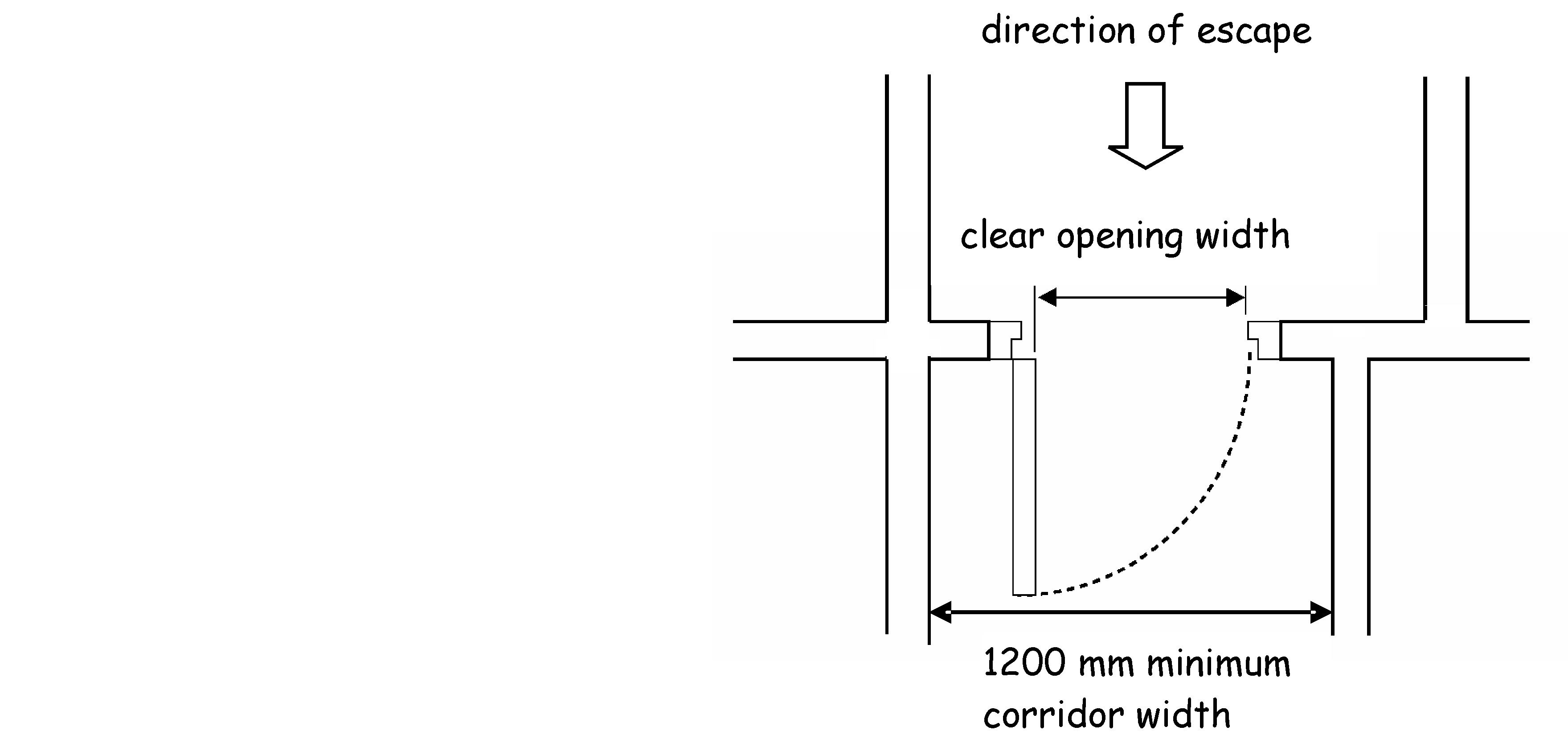
The guidance on the width of exits assumes a unit width of 530mm per person and a rate of discharge of 40 persons per minute. In theory a corridor 530mm wide would be capable of discharging 100 occupants in 2.5 minutes, but such a width would not allow occupants to move around freely and without difficulty, to the best of their ability. The unobstructed width of each individual escape route should be at least 1200mm to assist occupants with sensory, cognitive and/or mobility impairments. However where only stepped access is provided to a part of the building, the escape route may be reduced as follows:
Doorways can reduce the width of escape routes by 150mm. This nominal reduction allows for the construction of door frames, however:
-
where the number of occupants using the escape route is not more than 225, the clear opening width of the doorway should be at least 850mm
-
where the number of occupants using the escape route is not more than 100, the clear opening width of the doorway should be at least 800mm.
The clear opening width at doorways is measured in accordance with the diagram below:
Constancy of width - an escape route should not narrow in the direction of escape. However an escape route may pass through a wider circulation area leading to a narrower circulation area provided the latter is of a width at least that recommended for the escape route. Width of escape stairs is covered in clause 2.9.31.
The strict application of the above guidance may not be appropriate in all cases as follows:
-
a hospital, where staff will move bed patients into a safe area within the building, or
-
enclosed shopping centres where the mall is regarded as a place of relative safety.
More detailed guidance for hospitals is provided in annex 2.B and for enclosed shopping centres in annex 2.C.
Everyone within a room when confronted by an outbreak of fire should be provided with at least one means of escape that offers safe passage to an exit from that room.
A layout, which only follows the recommendations for travel distance and number of storey exits, may still result in an undesirable layout. For example if two exits are placed close together it may make it impossible for all occupants to reach either exit if the fire is close to the exits. It is essential therefore, that where more than one exit is provided they are located so that at least one exit is available.
In many cases, there will not be an alternative at the beginning of the route. For example, there may be only one exit from a room to a corridor, from which point escape is possible in two directions. This is acceptable provided the distance the occupants have to travel, to the point where they can diverge in two or more directions, follows the relevant guidance in clause 2.9.3 for one direction of travel, and the overall route to a protected zone or place of safety follows the recommendations for more than one direction of travel.
Where more than one room exit is provided, the directions of travel from any point within the room should:
-
diverge at an angle of at least 45°, or
-
be combined for a distance not more than that allowed for one direction of travel and then diverge to two exits at an angle of at least 45° plus 2½° for every metre travelled in one direction (see table to clause 2.9.3).
To reduce the risk of 2 room exits becoming impassable due to fire or smoke in the early stages of fire growth, the distance between the exits from the room should be more than twice the distance travelled in one direction.
2.9.10 Escape from inner room
Occupants within an inner room could become trapped where there is an outbreak of fire in the adjoining access room. Therefore, escape should only be by way of one other room, and the inner room should:
-
not be used as sleeping accommodation
-
have an escape route that does not pass through more than one access room
-
the access room should be fitted with a suitable automatic fire detection and alarm system to warn the occupants of the inner room of an out break of fire
-
the access room should not be a place of special fire risk.
Storage areas of buildings with fixed obstructions should provide unobstructed access to an exit. Access to an exit in such buildings may be by way of a gangway. The width of gangways between fixed obstructions (including fixed racking or shelving and high-bay storage) should be at least 530mm. Due to the low occupancy and limited occupation in a building for the bulk storage of spirituous liquor, the width may be reduced to at least 400mm.
Fixed seating or furnishings - in a building, or part of a building, with fixed seating or fixed seating and fixed tables or other floor fixtures, there should be access to an exit by way of a gangway or a seatway, or a seatway directly to an exit; or a circulation area in accordance with the table and diagram below and:
-
in the case of an auditorium that has more than 1 exit, at least 1 exit should be provided at least two-thirds of the distance from any stage, screen or performing area towards the back of the room, and
-
a gangway or exit door should be provided at each end of a row of more than 12 fixed seats, and
-
in the case of shops where the room, or part of the room, has an occupancy capacity of more than 100, the minimum width of a circulation area should be designed as if the circulation area were an escape route, or
-
in the case of buildings to which the Safety of Sports Grounds Act 1975 applies, it is appropriate to use the Guide to safety at sports grounds http://www.culture.gov.uk.

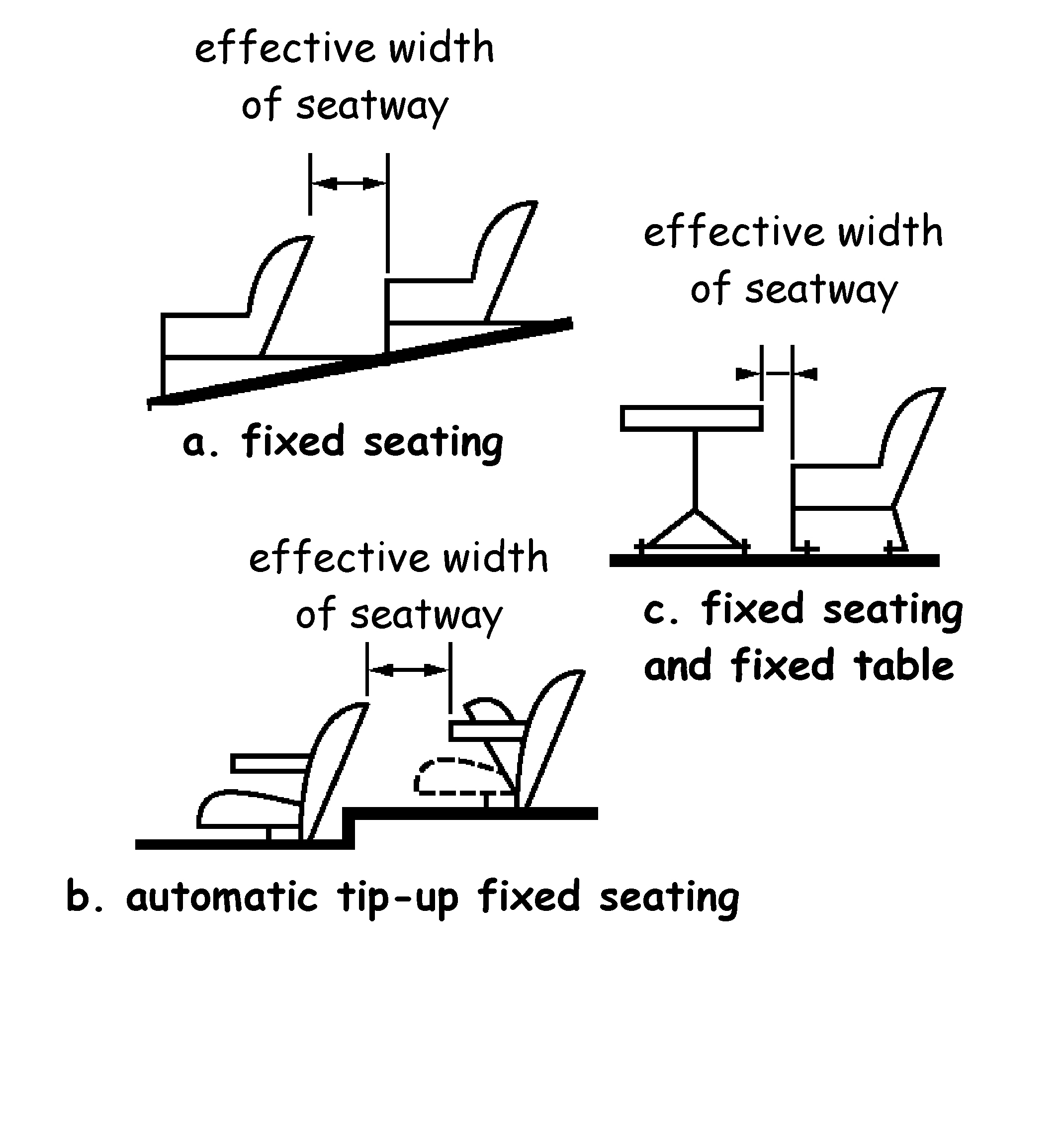
Table 2.14. Minimum width of gangways & seats in a room with fixed seating
| Situation | Number of seats in a row with Gangway one side | Number of seats in a row with Gangway on both sides | Minimum or effective width (mm) |
|---|---|---|---|
| Gangway | Not applicable | Not applicable | 1200 [1] |
| Gangway and seatway combined | Not applicable | Not applicable | 1350 |
| Seatway | 2 | 2-4 | Not applicable |
| Seatway | 3-7 | 5-14 | 300 |
| Seatway | 8 | 15, 16 | 325 |
| Seatway | 9 | 17, 18 | 350 |
| Seatway | 10 | 19, 20 | 375 |
| Seatway | 11 | 21, 22 | 400 |
| Seatway | 12 | 23, 24 | 425 |
| Seatway | - | 25, 26 | 450 |
| Seatway | - | 27, 28 | 475 |
| Seatway | - | More than 28 (limited by travel distance)[2] | 500 |
Additional information:
-
May be reduced to 900mm where the occupancy capacity of the room is not more than 60.
-
The travel distance should be measured by way of the shortest route along open seatways, gangways or circulation areas.
2.9.12 Escape routes in residential buildings
In residential buildings occupants are particularly vulnerable to fire when asleep. Occupants may also be unfamiliar with their accommodation and escape routes. Those occupants on the fire floor should be provided with the opportunity to reach a protected zone (or other escape route) in relative safety and as quickly as possible, therefore, the movement of fire and smoke to the escape route should be inhibited.
In a residential building, where any corridor escape route serves sleeping accommodation it should be constructed of walls providing a short fire resistance duration and any door in the wall should be a suitable self-closing fire door with a short fire resistance duration. However the fire door to the cleaners cupboard need not be self closing provided it is lockable.
This guidance may need to be adapted in a residential building used as a place of lawful detention due to the unique operational factors.
For additional guidance on residential care buildings and hospitals see annex 2A and 2B.
The first hazard to occupants beyond the room of fire origin is likely to be from the products of combustion. Any migration of fire and smoke to an escape route may deter occupants from using it.
Every corridor, that is used as an escape route that exceeds the dimensions in the guidance below, should be:
-
subdivided with a wall or screen with a short fire resistance duration, or
-
protected by the installation of a smoke control system.
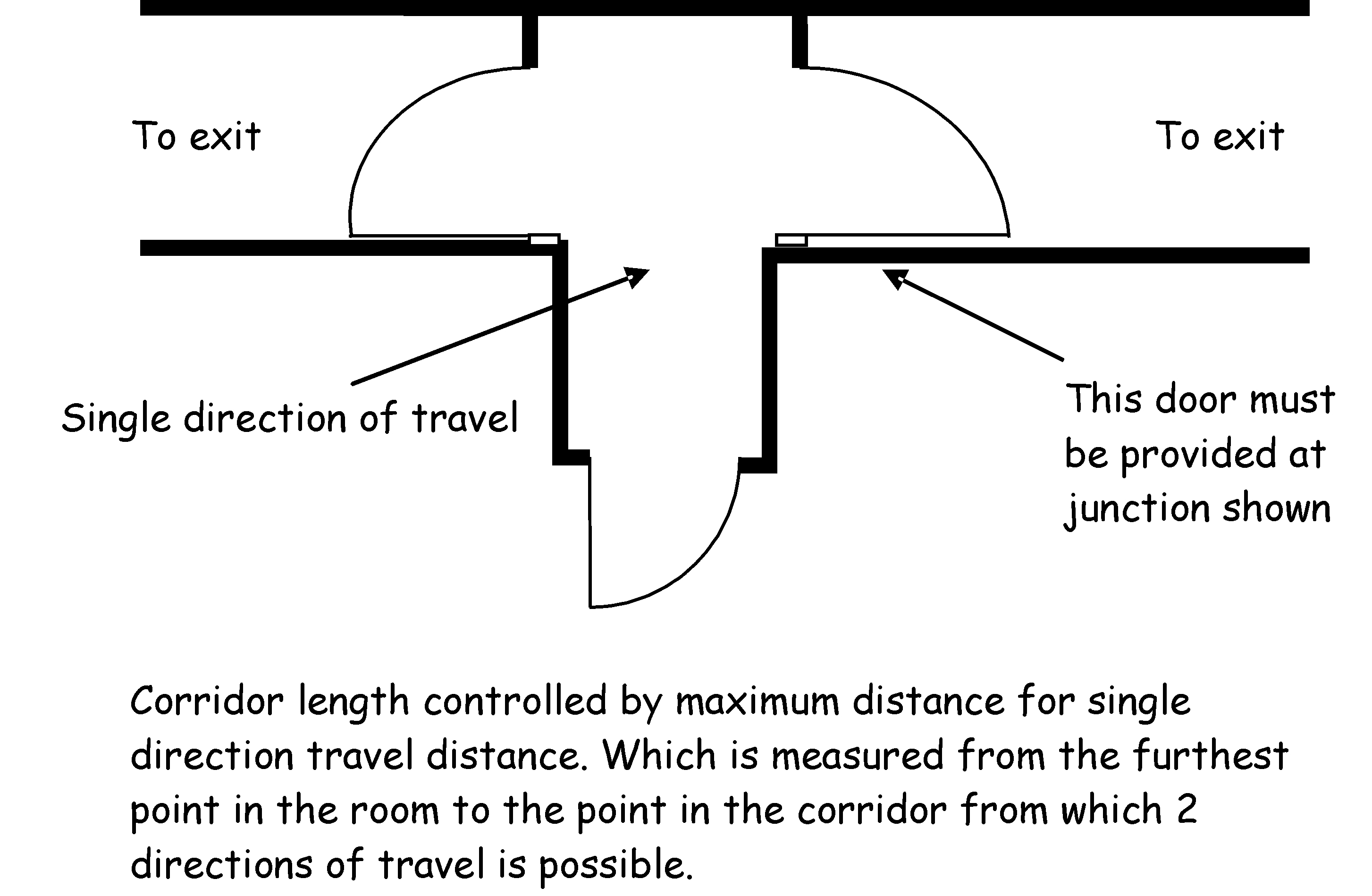
Where the corridor is subdivided by a wall or screen with a short fire resistance duration (insulation criteria need not be applied) any door in the wall or screen should be a self-closing fire door and:
-
where the corridor is a dead end more than 4.5m long and provides access to a point from which more than 1 direction of escape is possible, it should be divided at that point or points, as shown in the diagram below and
-
where the corridor provides at least 2 directions of escape and is more than 12m in length between the exits it serves, it should be divided in the middle third of the corridor. This does not mean that the corridor should be subdivided into 12m lengths.
Where a cavity extends across any of the self closing fire doors identified above, or above the walls described in clause 2.9.12 a cavity barrier with at least short fire resistance duration should be fitted above the sub-dividing wall and fire door to inhibit fire and smoke spread.
Smoke control systems - when a design incorporates a smoke control system in a building, other than a residential care building or hospital, it should employ smoke differentials in accordance with BS EN 12101: Part 6: 2005, but assuming a minimum pressure difference (over the wall being assessed) of 25 Pa based on a wind speed of 22m/sec. Mechanical smoke ventilation using pressure differentials may be used to inhibit smoke spread into escape routes by means of:
-
depressurisation systems, or
-
pressurisation systems.
The merits and limitations of each system should be assessed before deciding which system to choose.
A depressurisation system is based on the principle of extracting smoke to the outside air. This creates a negative pressure in the space relative to the adjacent spaces. Where a smoke ventilation depressurisation system is used, replacement air should be provided for the system to operate effectively. The volume of air and smoke removed should be replaced with the equivalent volume of replacement air at a sufficient rate in order to ensure a smoke flow out of the building. Reducing the rate of replacement air can result in the smoke ventilation system becoming less efficient whereas increasing replacement air and extraction at high velocities can produce air pressure conditions which make doors difficult to open. The system should be balanced to ensure that the forces required to open doors are not greater than those specified in Section 4 Safety.
A pressurisation system is based on the principle of forcing air into the escape route which helps to keep smoke out. Forced air can be used to maintain a positive pressure in the escape route which produces an air flow through gaps around doors preventing the smoke from entering. The system design should take account of likely pressure reduction when occupants open doors to escape or when fire-fighters open doors to access the fire. The system should be balanced to ensure that the forces required to open doors are not greater than those specified in Section 4 Safety.
In the event of a fire, there is always a risk that an opening in a floor could result in a proportion of fire or smoke and toxic fumes arising from a fire flowing up through the opening leading to a build-up of smoke on the upper storeys. This can pose a threat to life safety, particularly when the occupants are unfamiliar with the building. Smoke and flames rising through such an opening in a floor may impede evacuees from leaving the building. It is important when such a design is considered that it does not impair the ability of the occupants to escape. Occupants should be able to move directly away from the opening or continue their evacuation at a safe distance away from the edge of the opening.
Escape routes should not be compromised by openings between floors, such as at an escalator and fire safety measures are necessary to compensate for this increased level of hazard; the diagram below explains this principle.
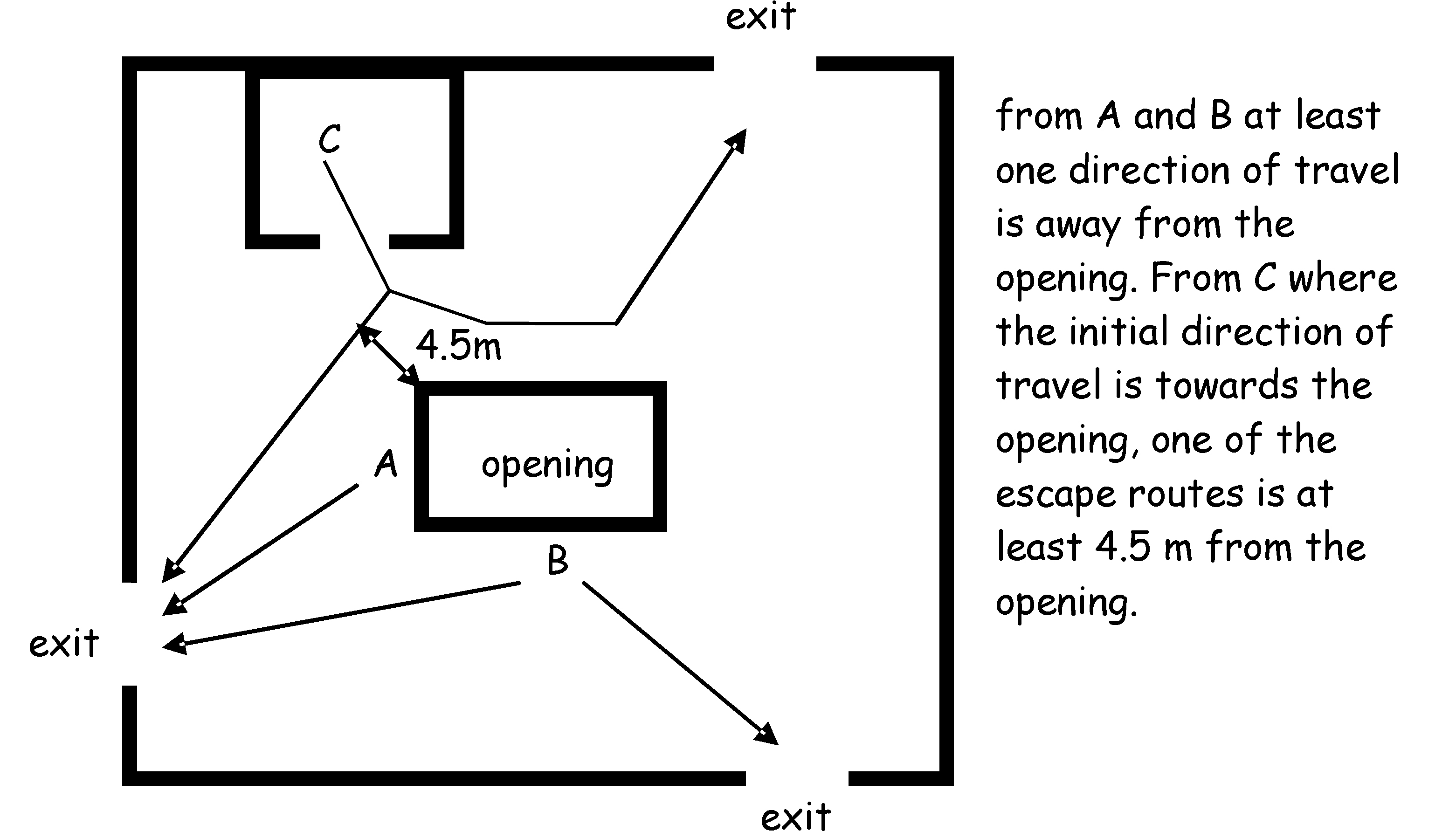
In a building where there is an opening in any floor, not being a compartment floor or separating floor, an escape route should not be within 4.5m of the openings unless:
-
the direction of travel is away from the opening, or
-
there is an alternative escape route, which does not pass within 4.5m of the opening, or
-
a wall or screen with a short fire resistance duration for integrity is provided between the opening and the route of escape.
Time can be a critical factor in ensuring occupants can leave the building before being overcome by the effects of fire and smoke. It is important therefore that an escape route provides a clear unobstructed route that does not restrict the flow of occupants.
To ensure the safe and smooth movement of occupants and prevent unnecessary increase in anxiety during an evacuation the following should not be part of an escape route:
-
a lift, or
-
an escalator, or
-
a turnstile, other than a suitably designed and installed turnstile unit with an emergency break out facility enabling the entire unit to open in the direction of escape, or
-
any shutter; other than one which is installed for security purposes across a shop front and which does not close automatically in the event of fire, or
-
a manual sliding door, accessible to the public.
A fixed ladder may be used to escape from a plant room (not being a place of special fire risk), which is unoccupied other than for maintenance purposes.
Revolving doors and automatic doors can obstruct the passage of persons escaping. However they may be installed in an escape route if designed and installed in accordance with BS 7036: 1996 and are either:
-
arranged to fail safely to outward opening from any position of opening, or
-
provided with a monitored fail-safe system for opening the door from any position in the event of mains supply failure and also in the event of failure of the opening sensing device, and
-
opens automatically from any position in the event of actuation of any fire alarm in the fire alarm zone within which the door is situated.
Doors across an escape route can slow the flow of occupants and may lead to crowding. To ensure that doors on an escape route do not unduly delay escape they should open in the direction of escape. However doors across an escape route may open against the direction of escape where the occupancy capacity in the building, or part of the building is low as follows:
-
in a factory building or storage building where the occupancy capacity is not more than 10
-
in any other building where the occupancy capacity is not more than 60.
However if the door is an emergency door or a door serving a place of special fire risk, the side-hung door should open in the direction of escape regardless of occupancy levels.
For the purposes of compliance with this standard a gallery is an integral part of the room into which it projects, and the occupants of a gallery would have the same awareness of an outbreak of fire in a room as the other occupants of that room. The limitations on the size of a gallery relative to the room into which it projects is to provide those occupants on the gallery with the same awareness of any outbreak of fire.
The safety of those using a gallery, relates to:
-
the use and occupancy characteristics within the room, and
-
the occupancy capacity, and
-
the travel distance, and
-
the number of escape routes.
A gallery should be open above and below to the room into which it projects and should not give access to any other room, other than a room with a means of escape independent of the gallery. The gallery may be wholly or partly enclosed below, where:
-
the floor of the gallery has a short fire resistance duration, and
-
at least 1 route of escape from the gallery is by way of a protected door.
Locks on exits doors or locks on doors across escape routes present difficulties when assessing the need for security against the need to allow safe egress from a building in the event of a fire. Security measures however should not compromise the ability of the occupants to escape from a building in an emergency.
In general, all doors on escape routes, should either not be fitted with locks, or they should only be fitted with fastenings that can be readily operated from the side approached by occupants making an escape. The operation of these locks should be readily apparent, without the use of a key or access control tokens and without having to manipulate more than one mechanism. This is not intended to prohibit the use of locks to secure a room, storey or building when unoccupied. This guidance may also need to be adapted in a building used as place of lawful detention due to the unique operational factors.
Where an exit door from a room, storey or a door across an escape route has to be secured against entry when the building or part of the building is occupied, it should only be fitted with a lock which is readily operated, without a key, from the side approached by occupants making their escape. Similarly, where a secure door is operated by a code, combination, swipe or proximity card, biometric data or similar means, it should also be capable of being overridden from the side approached by occupants making their escape (see also electrically operated locks).
Guidance on the types of hardware for timber fire and escape doors can be obtained from the Code of Practice, 'Hardware for Fire and Escape Doors' Issue 2, June 2006, published by the Door and Hardware Federation and the Guild of Architectural Ironmongers.
2.9.19 Mechanical or electro-mechanical panic exit locking devices
Different groups of users will have differing needs to enable them to escape quickly and easily from a building in the case of fire and this should be reflected in the type of lock chosen. For example, in buildings frequented by the general public it is important that the locks can be released by occupants who may be unfamiliar with the building and have received no training in the emergency procedures or the types of exit locks used in the building.
These locks are designed to operate on body pressure alone and require no knowledge of their operation to enable safe and effective evacuation of the building. In these cases, panic exit locks operated by a horizontal bar should be designed and installed in accordance with BS EN 1125: 1997.
2.9.20 Mechanical or electro-mechanical emergency exit locking devices
In buildings, or parts of buildings, that are not open to the general public, such as in offices or other working environments, the occupants should be awake and familiar with the building. When staff in such areas are trained both in the emergency procedures and in the use of the specific emergency devices fitted (see clause 2.0.8) then emergency exit devices to BS EN 179: 1997 can be installed. This type of locking device is released mechanically by a single action applied to the door lever handle or push pad to allow people familiar with the building to escape in an emergency.
Locking devices to BS EN 179: 1997 can also be used in buildings or areas used by the general public where the occupancy capacity is low. Therefore these devices should not be installed on any door accessible to the general public where the aggregate occupancy capacity of the rooms or storeys served by the door is more than 60 persons.
Where there is a choice of escape routes and the doors on one direction of escape are fitted with devices giving mechanical escape which operate on body pressure alone to BS EN 1125: 1997 or by the use of a lever handle or push pad to BS EN 179: 1997, the alternative escape route could be fitted with fail unlocked, electric locking device, such as an electro-magnetic lock. These are devices that require electrical power to be withdrawn from them to unlock.
Fail unlocked, electric locks, may be installed on exit doors and doors across escape routes, which are inaccessible to the general public or, on any door accessible to the general public where the aggregate occupancy capacity of the rooms or storeys served by the door does not exceeds 60 persons.
Where the locks are intended to be used by occupants who are familiar with the building, staff in such areas, will need to be trained both in the emergency procedures and in the use of the specific locking devices fitted (see clause 2.0.8). Fail unlocked devices are not designed to be used by people in a panic.
Where installed in buildings that feature fail unlocked electric locks, they should operate in conjunction with a fire alarm system, the design of which should be determined by a fire risk assessment (see clause 2.0.8).
More detailed guidance on the type of fire alarm system most appropriate to the circumstances is contained in BS 5839: Part 1: 2002.
This type of ‘fail unlocked electric locking device’ should unlock instantly when electrical power is withdrawn and should unlock even when pressure is being applied to the escape door by occupants trying to escape at the time that electrical power is withdrawn.
‘Fail unlocked electric locks’ should not be installed on:
-
a protected door serving the only escape stair in the building (or the only escape stair serving part of the building), or
-
a protected door serving a fire-fighting shaft, or
-
on any door which provides the only route of escape from the building or part of the building, or
-
on any door accessible to the general public where the aggregate occupancy capacity of the rooms or storeys served by the door exceeds 60 persons.
A delay in the opening of a door across an escape route, can lead to an increase in anxiety of occupants or possible panic. Therefore ‘fail unlocked electric locks’ should be programmed to fail to the unlocked position:
-
on operation of the fire alarm system
-
on loss of electrical power or system error
-
on activation of a manual door release unit (Type A) to BS EN 54: Part 11: 2001 they are connected to, positioned at the door on the side approached by occupants making their escape and where the door provides escape in either direction, a unit should be installed on both sides of the door.
Some electric locking devices fail locked on both sides of the door when electrical power is withdrawn and does not give mechanical escape by panic bar, handle or push pad. This type of electric locking should not be used on exit doors and doors across escape routes.
In a building containing an auditorium, a ventilation system should be provided above all stages so that in the event of fire the occupants can escape before being overcome by the effects of fire or smoke. The ventilation system should be designed in such a way that the direction of air movement in the event of fire is from the auditorium towards the stage. Ventilation may be provided by means of mechanical extract ventilation or by natural ventilation direct to the external air, additional guidance is provided in BS 5588: Part 6: 1991.
Escape from the part of the stage behind the safety curtain should be independent from that of the auditorium.
Ancillary fire hazard rooms in the stage area, such as scenery dock, workshop, stage basement, staff or other rooms associated with the stage should where reasonably practicable be enclosed by a construction with a short fire resistance duration.
In a building containing an auditorium having an occupancy capacity of more than 500, additional passive and active fire safety measures should be provided and any stage should be separated from the remainder of the building by walls of medium fire resistance duration.
However this does not apply to the following:
-
the proscenium opening, provided there is a safety curtain which conforms to BS 5588: Part 6: 1991, and
-
an open stage.
Any door openings in the proscenium wall other than the proscenium opening should be provided with protected lobbies with short fire resistance duration.
Where a stage is equipped with a safety curtain, a high level outlet over the stage and stage area should be provided to allow the safety curtain system to operate effectively by containing fire and smoke to the stage and to allow the escape of smoke and hot gases in the event of a fire on the stage.
Where a building has an open stage the smoke exhaust system should be sized to keep the auditorium relatively clear of smoke during the period of evacuation. Extract ventilation should preferably be taken from high level positions to assist in keeping the main auditorium clear of smoke. The size and performance of the smoke exhaust system will depend upon the size of the stage. Unless determined otherwise by a fire engineering calculation, natural exhaust ventilators over an open stage should have a combined total aerodynamic free area of at least 10% of the area of the stage.
Each case should be considered separately to ensure that smoke will not be transferred from one area to another, particularly where there are distinctly separate entertainment areas, which share common escape routes.
2.9.23 Protected lobbies
A protected lobby is located within a protected zone and is designed to inhibit the movement of fire and smoke from an adjoining room, storey or space into the escape stair or fire-fighting lobby. This is normally achieved by fire resisting construction together with at least 2 sets of self-closing fire doors between the fire and the escape stair or fire-fighting lobby.
Protected lobbies in non-domestic buildings are used:
-
to inhibit fire and smoke spread to escape stairs
-
to help occupants escape past the floor of fire origin
-
to provide a protected route of escape from the fire floor
-
to reduce the number or width of escape stairs in a building
-
to provide a relatively safe space for the fire and rescue services to set up a forward control point and to provide a bridgehead from which to commence operations (see Standard 2.14).
Buildings with 1 Escape route - occupants in buildings with only 1 escape route are at greater risk from being exposed to fire and smoke during their escape. Therefore, where a building has only 1 escape route by way of an escape stair, access to the escape stair should be by way of a protected lobby.
There is less risk in low rise non-residential buildings with low occupancy numbers, which have a fire warning and detection system installed as this should provide the occupants with sufficient time to escape. The occupants of such buildings should be awake, and have less distance to travel. Therefore, a protected lobby need not be provided where the building:
Occupants in tall buildings will take longer to escape from the building and are therefore at greater risk from being exposed to fire and smoke during evacuation. There is also the risk that more than 1 escape stair could be affected by fire or smoke. Therefore, in every building having a storey at a height of more than 18m above ground level, access to the protected zone containing the escape stair should be by way of a protected lobby. When a protected lobby is provided, the wall dividing a protected lobby from the remainder of the protected zone should have a short fire resistance duration for integrity only and any door in the wall should be a self-closing fire door with a short fire resistance duration. However see Standard 2.14 for fire and rescue service facilities.
2.9.24 Protected zones
A protected zone may or may not contain an escape stair and is intended to protect occupants during their evacuation to a place of safety.
Protected zones should be designed and constructed to withstand fire in an adjoining room or space. The protected zone should form a complete enclosure having at least a medium fire resistance duration. Every door in the wall of a protected zone should be a self-closing fire door with a medium fire resistance duration. However the floor of the lowest storey or an external wall (other than an external wall described in clause 2.9.36) need not be fire resistant.
Shared residential building - a protected zone in shared residential accommodation should have at least short fire resistance duration.
As a building becomes taller the distance to be travelled and time taken for the occupants to reach a place of safety increase. Therefore in buildings with any storey at a height of more than 18m, the enclosing structure of the protected zone should have long fire resistance duration on all storeys.
The accommodation within every protected zone should be limited to places where fire is unlikely to start. As the fire risk is considered low, a cleaners cupboards of not more than 3m2 and toilets or washrooms may be sited in the protected zone.
In buildings with 2 or more protected zones, the occupants have an alternative route out of the building if one of the protected zones was affected by fire or smoke. A reception room, an office and a general store room, each of not more than 10m2 may be located within the protected zone as they are of limited size and the potential fire load is low.
The wall separating the rooms/cupboards from the protected zone should have a short fire resistance duration and any door in the wall should be a self-closing fire door. A door to a cleaner’s cupboard need not be self-closing provided it is lockable. The walls/doors separating the toilets or washrooms from the protected zone need not have a fire resistance duration.
To protect occupants from fire and smoke when evacuating a building, an escape stair should be within a protected zone. However this is not necessary in the following situations:
-
an escape stair which connects 2 or more levels within a single-storey where the difference in level between the highest and lowest level is not more than 1.8m, or
-
an external escape stair with a total rise of not more than 1.6m, or
-
an external escape stair constructed in accordance with clause 2.9.37
-
an escape stair, from a gallery, catwalk (including lighting bridges), or openwork floor where they have:
-
an occupancy capacity of not more than 60, or
-
an occupancy capacity of more than 60 but not more than 100 and at least 1 route of escape is by way of a protected zone, an external escape stair or to another compartment. Where the occupancy capacity is more than 100 the escape stair should be enclosed within a protected zone.
-
Due to a very high fire risk, with potential for rapid fire growth, a place of special fire risk should only be accessed from a protected zone by way of a protected lobby. This is to give additional protection to the protected route of escape.
Fire and smoke can easily pass through openings in protected routes of escape (see clause 2.0.6) which could prevent the occupants from escaping in the event of an outbreak of fire within the building. For this reason, the openings in protected routes of escape should be limited to openings such as smoke ventilation systems, chimneys, flue-pipes, self-closing fire doors and service openings, fire shutters or dampers.
It is important that ducted heating and ventilation systems including air conditioning systems, installed to maintain interior environment conditions, that serve the building should not transfer fire and smoke to or from; any compartment to any other compartment, escape route, common space, roof space or other concealed space. Therefore, in the event of an outbreak of fire, the system should automatically either shut off, or operate in smoke control mode. For more detailed guidance refer to BS 5588: Part 9: 1999.
In order to inhibit the spread of fire and smoke, the openings should be protected and fire stopped in accordance with the guidance to Standard 2.1.
The junctions between protected routes of escape (see clause 2.0.6) and other parts of the building are vulnerable to fire and smoke. This is because fire and smoke can penetrate weaknesses at junctions which could compromise the means of escape. The designer should consider detailing at junctions to inhibit fire and smoke spread into the protected route of escape.
Where part of a building is a protected route of escape and forms a junction with any other part of the building including for example, an external wall, a separating wall, another compartment wall, or any other wall or screen forming a protected route of escape, the junction should maintain the fire resistance duration of the more demanding guidance.
In order to inhibit the spread of fire and smoke, junctions should be protected in accordance with clause 2.1.15 and for additional guidance on fire-stopping materials, see clause 2.1.14.
Pipes conveying fuel inside protected zones could accelerate fire growth and under certain conditions, create an explosive atmosphere within the building. Oil and liquefied petroleum gas can produce pool fires, i.e. a turbulent fire burning above a horizontal pool of vaporising hydrocarbon fuel. The pool fire can be either static e.g. where the pool is contained or a ‘running’ pool.
Fuel pipes carrying oil (other than a pipe conveying oil supplying a hydraulic lift) should be located outside protected zones. A pipe conveying oil supplying a hydraulic lift may be located inside a protected zone. Fuel pipes carrying natural gas or liquefied petroleum gas (including associated meters) may be located within a protected zone provided:
-
the installation is in accordance with the requirements of the Pipelines Safety Regulations 1996, SI 1996 No 825 and the Gas Safety (Installation and Use) Regulations 1998 SI 1998 No 2451, and
-
any pipe is constructed of screwed steel or welded steel construction, and
-
the pipe or pipes are contained within a service shaft with at least a medium fire resistance duration from the outside, and
-
the service shaft is ventilated at high and low level in accordance with BS 8313: 1997.
The speed of evacuation of occupants with sensory, cognitive and/or mobility impairments can be much slower than other building users. Therefore, a space should be provided to allow them to wait temporarily, before completing their escape to a place of safety.
The safe evacuation of occupants with sensory, cognitive and/or mobility impairments is the responsibility of the employer or other person having control of the building and not that of the fire and rescue service. Therefore, occupants with sensory, cognitive and/or mobility impairments, should not be directed to remain in these spaces awaiting the arrival of the fire and rescue service. The employer or other responsible person should make the necessary arrangements for the safe evacuation of all occupants from the temporary waiting spaces.
The duty holder also has a duty under the Management of Health and Safety at Work Regulations 1999, to assess the risks to workers and any others, who may be affected by their work or business. Further requirements under the Fire (Scotland) Act 2005 and the Fire Safety (Scotland) Regulations 2006, in respect of fire safety risk assessment and further obligations in respect of fire safety measures must also be considered.
Temporary waiting spaces should have an unobstructed clear area capable of accommodating a wheelchair and measuring at least 700mm x 1200mm. They should be located in either:
-
a protected lobby, or
-
a protected zone, or
-
an external escape stair, or
-
an adjacent compartment.
However it is not necessary to provide a temporary waiting space in a protected zone where the storey has level or ramped egress to a place of safety or on an external escape stair with a total rise of not more than 1.6m.
To assist the escape process and reduce the anxiety of occupants making use of the space, an emergency voice communication (EVC) system should also be provided in the designated temporary waiting space.
The EVC should follow the guidance in either:
-
BS 5839: Part 9: 2003 and consist of type B outstations and communicate with a master station located in the building control room (where provided) or adjacent to the fire alarm panels, or
-
in some buildings, it may be more appropriate to use alternative two way communication that can be readily operated by occupants in the temporary waiting space.
2.9.31 Escape stair widths
Every escape stair should be wide enough to accommodate the number of occupants needing to use it in an emergency and allow them to make their escape before being overcome by the effects of fire and smoke. This width will depend on the number of stairs provided and whether the escape strategy for the building (or part of the building) is based on:
-
simultaneous evacuation, or
-
phased evacuation.
Minimum effective width - to help limit the potential for queuing at the storey exit which in an emergency may lead to panic and crushing, the effective width of an escape stair should be at least the width of any escape route giving access to it. Therefore the effective width of each escape stair should be at least 1200mm to assist occupants with sensory, cognitive and/or mobility impairments. However where the building has limited occupancy numbers the escape stair width may be reduced as follows:
-
1100mm where the number of occupants using the stair is not more than 225, and
-
1000mm where the number of occupants using the stair is not more than 100.
The effective width of an escape stair is measured between handrails and clear of obstructions.
Where the number of occupants using the escape stair is more than 225 then the formula for calculating the effective width of the stair should be used. The escape stair should not narrow in the direction of escape.
Appropriate capacity - to assist the verifier and designer establish the width of an escape stair, it is necessary to establish the number of escape stairs and the number of occupants who will access them on each storey. The effective width of escape stairs is based on the number of occupants who will use each escape stair and the resultant figure is known as the appropriate capacity (AC). The methodology for calculating the appropriate capacity must also take into account whether a building has been based on simultaneous or phased evacuation.
Simultaneous evaluation - in a building designed on the basis of simultaneous evacuation the escape stairs (in conjunction with the rest of the means of escape) should have the capacity to allow the occupants of all storeys to evacuate at the same time.
The appropriate capacity in relation to an escape stair at any storey above or below the adjacent ground is calculated by one of the following methods.
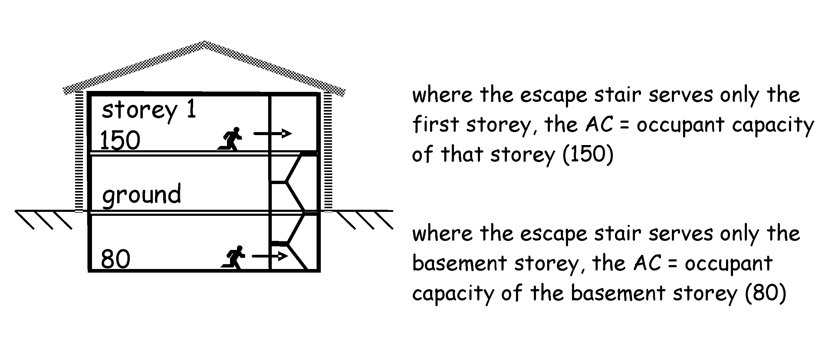
Where the escape stair serves only one storey, the appropriate capacity equals the occupancy capacity of the storey served by the escape stair (see diagram below). The appropriate capacity for the storey should then be used in the formula for calculating the effective width of the escape stair.
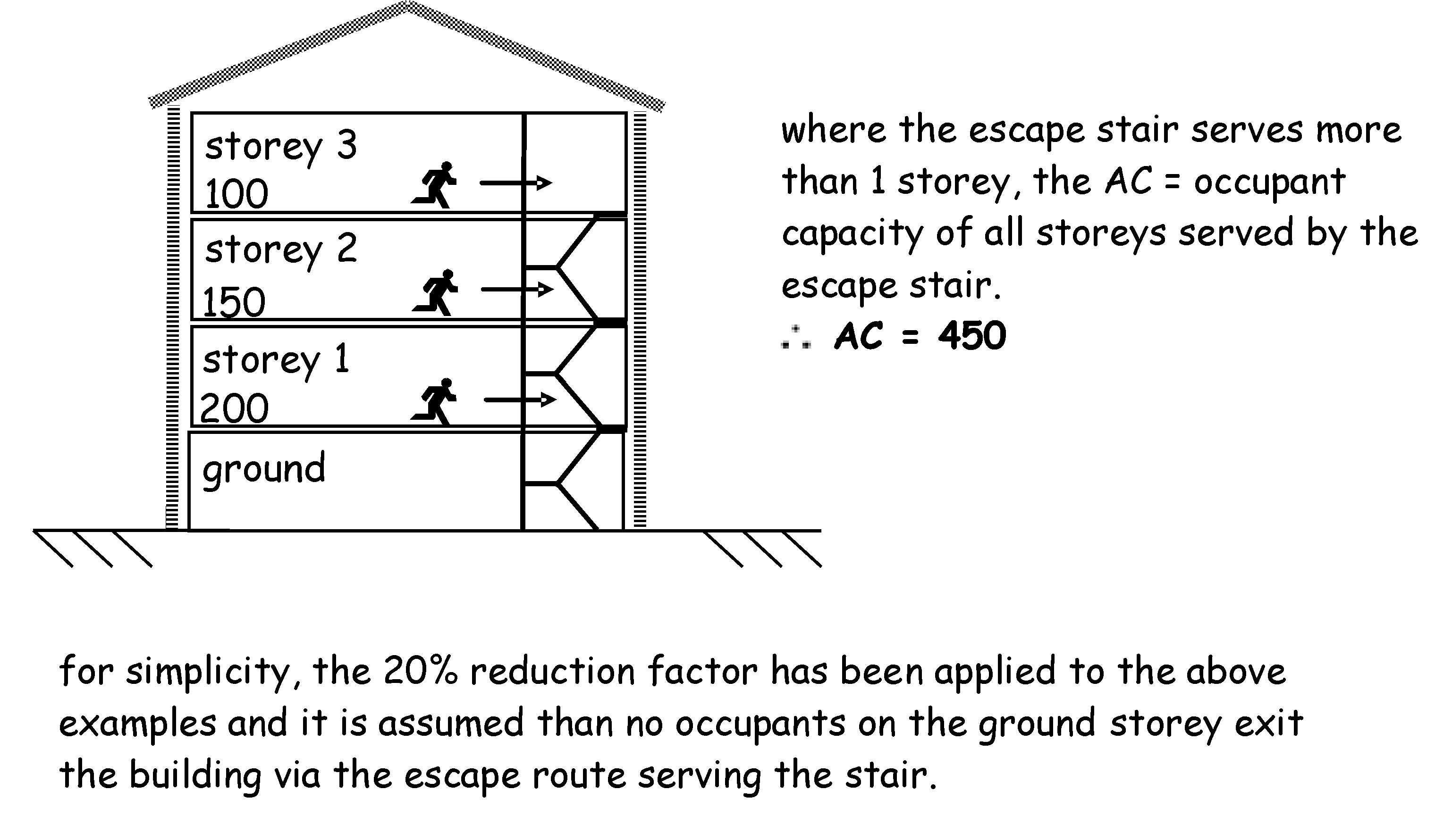
In a building in which the escape stair serves more than 1 storey the appropriate capacity for each storey should be calculated and the total appropriate capacity for all the storeys served by the escape stair should then be used in the formula for calculating the effective width of the escape stair. A deduction of 20% from the appropriate capacity is allowed for the number of occupants who could be standing in the stair.
This method of calculating the escape stair width can be used to reduce the width of the stair as it rises up the building although this would not be a typical form of construction.
Phased evacuation allows occupants most at risk to be evacuated first. This allows the designer to reduce the width of the escape stairs and minimises disruption in large buildings. Tall buildings take longer to evacuate and where the building is at a height of more than 25m it is beyond the reach capability at which Fire and Rescue service can effect external rescue. Therefore, when phased evacuation is adopted in buildingsadditional active and passive fire protection measures will be necessary.
As phased evacuation relies on some occupants remaining where they are until instructed to leave, it is only suitable for buildings where the occupants are awake and familiar with the building, for example, offices.
The occupants first evacuated are those on the storey of fire origin and those on the storey immediately above. If further evacuation is required this is done on the basis of the next two adjoining upper storeys to avoid congestion in the escape stairs. The remaining storeys would then be evacuated two storeys at a time however this would be dependent on the severity of the fire and any direction given by the fire and rescue service.
Because of the additional time it may take to evacuate a building or part of a building where the means of escape is based on vertical phased evacuation, the following fire safety measures should be provided:
-
installation of an automatic fire detection and alarm system to BS 5839: Part 1: 2002, Category L2, and
-
a voice alarm should be installed in accordance with BS 5839: Part 8: 2008. Such a system enables two or more stages of alarm to be given within a particular area, and
-
the escape stairs should be entered from a protected lobby, and
-
every storey should be a compartment storey, and
-
if the building has any storey at a height of more than 25m, every storey should be protected by an automatic life safety fire suppression system (see guidance to Standard 2.15), and
-
an internal speech communication system should be provided via a control point at the access level to allow the fire and rescue service to converse with a fire warden on every storey.
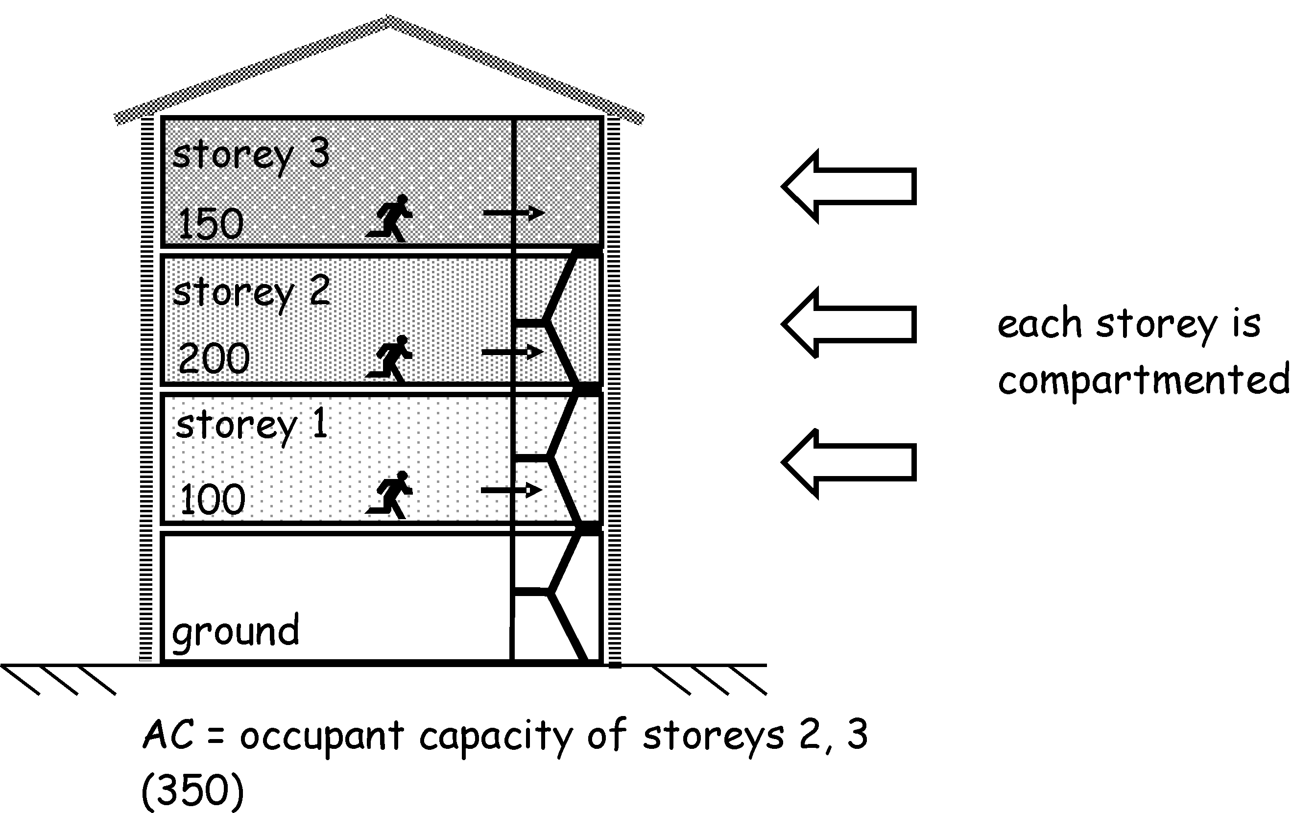
In a building where the stairs have been designed on the basis of vertically phased evacuation the appropriate capacity [AC] in relation to an escape stair at any storey above or below the adjacent ground is calculated by the following method and in accordance with the diagram below.
In a building, or part of a building, which is divided by one or more compartment floors, the appropriate capacity [AC] is equal to, the total occupancy capacity, less 20%, of each of the 2 adjacent upper storeys, served by the escape stair, or in the case of an escape stair serving a basement storey, the 2 adjacent basement storeys served by that escape stair, having in either case the greatest combined occupancy capacity.
Calculation of effective width - based on the above principles for simultaneous and phased evacuation, the effective width of every escape stair in mm can be calculated by the following formula:
Where:
-
EW is the effective width of an escape stair measured in mm between handrails and clear of obstructions
-
AC is the appropriate capacity, which in relation to an escape stair is the occupancy capacity of the storey served by the escape stair, less 20%
-
N - 1 is the number of escape stairs minus 1, unless it meets exception for protected lobbies above
A deduction of 20% from the appropriate capacity is made to allow for the number of occupants who could be standing in the stair.
Before using the formula it is necessary to consider the possibility that one stair may be affected by fire or smoke before all occupants have evacuated the building. For that reason one stair should be discounted for calculation purposes, unless a protected lobby is provided on every storey between each escape stair in a protected zone and any part of the building at any storey from which there is access to the escape stair.
If the escape stair contains any of the rooms listed in clause 2.9.24 the stair should be discounted from the stair width calculation.
Example 1 - simultaneous evacuation
What is the minimum effective width needed for escape stairs in an office building with 4 storeys and 2 escape stairs and which escape is based on simultaneous evacuation? For this example it is assumed that the occupants are distributed evenly across each storey, therefore the number of occupants will be split evenly to each escape stair.
There are 100 occupants on the top storey, 150 occupants on the 2nd storey and 200 occupants on the 1st storey. The escape routes on the ground storey do not communicate with the escape stairs.
It is assumed that the buildings do not have any protected lobbies, therefore the effective width equals:
AC is the appropriate capacity and is the sum of the occupancy capacity of the storeys served by the escape stair minus 20% for standing capacity in the stair:
Top storey = 100 x 0.8
2nd storey = 150 x 0.8
1st storey = 200 x 0.8
AC = 360
=
The minimum width of each escape stair will be 1908mm.
Example 2 - simultaneous evacuation
What is the minimum effective width needed for escape stairs in an office building with 6 storeys and 3 escape stairs and which escape is based on simultaneous evacuation. For this example it is assumed that the occupants are distributed evenly across each storey, therefore the number of occupants will be split evenly to each escape stair.
Each storey has 300 occupants and the escape routes on the ground storey do not communicate with the escape stairs.
It assumed access to each protected zone containing the escape stair is by way of a protected lobby. Therefore, there is no need to deduct 1 stair from the calculations:
AC is the appropriate capacity and is the sum of the occupancy capacity of the storeys served by the escape stair minus 20% for standing capacity in each of the stairs.
There are 5 storeys accessing the escape stair and each storey has 300 occupants the appropriate capacity is found by:
AC = 300 x 5 x 0.8
AC = 1200
=
The minimum width of each escape stair will be 2120mm.
Example 3 - phased evacuation
What is the minimum effective width needed for escape stairs in an office building with 10 storeys and 3 escape stairs and which escape is based on phased evacuation. For this example it is assumed that every storey is a compartment storey and that the occupants are distributed evenly across each storey, therefore the number of occupants will be split evenly to each escape stair.
Each storey has 300 occupants and the escape routes on the ground storey do not communicate with the escape stairs.
As escape is based on phased evacuation, access to each protected zone containing the escape stair should be by way of a protected lobby. Therefore, there is no need to deduct 1 stair from the calculations:
AC is the appropriate capacity of each of the 2 adjacent upper storeys, with the greater occupancy capacity, minus 20% for standing capacity in each of the stairs:
AC = (300 x 0.8) + (300 x 0.8)
AC = 480
=
EW = 848mm
However as the effective width of each escape stair should be at least 1200mm all 3 stairs should be at least 1200mm wide.
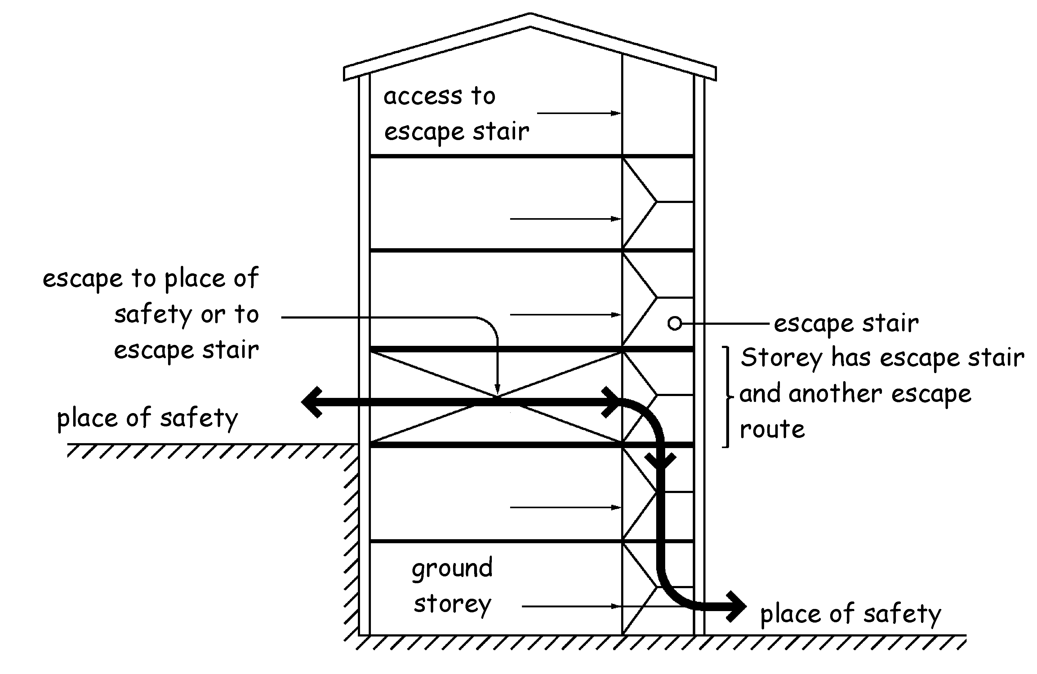
Combined escape routes - where escape routes from a storey consist of a combination of escape stairs and other escape routes (see diagram below) the effective width of any escape stair from that storey should be designed to take into account that proportion of the number of occupants on that storey who may escape by way of the other escape routes.
The escape route should be sized to take account of all the occupants who will be escaping. Therefore, where the escape route from an escape stair is also the escape route from the ground storey and/or basement storey, the width of that escape route should be increased to take account of that proportion of the occupancy capacity from the ground storey and/or basement storey.
Where there are alternative escape stairs from a storey, there is the risk that one of the escape stairs could be smoke logged preventing access through to the alternative escape stair. Where a room or storey needs two or more escape stairs, it should be possible to reach 1 alternative escape stair without passing through the other.
When the escape stairs are adjacent to one another, to reduce the likelihood of them becoming smoke logged at the same time, for example, where the protected zones enclosing escape stairs share a common wall, any access between them should be by way of a protected lobby.
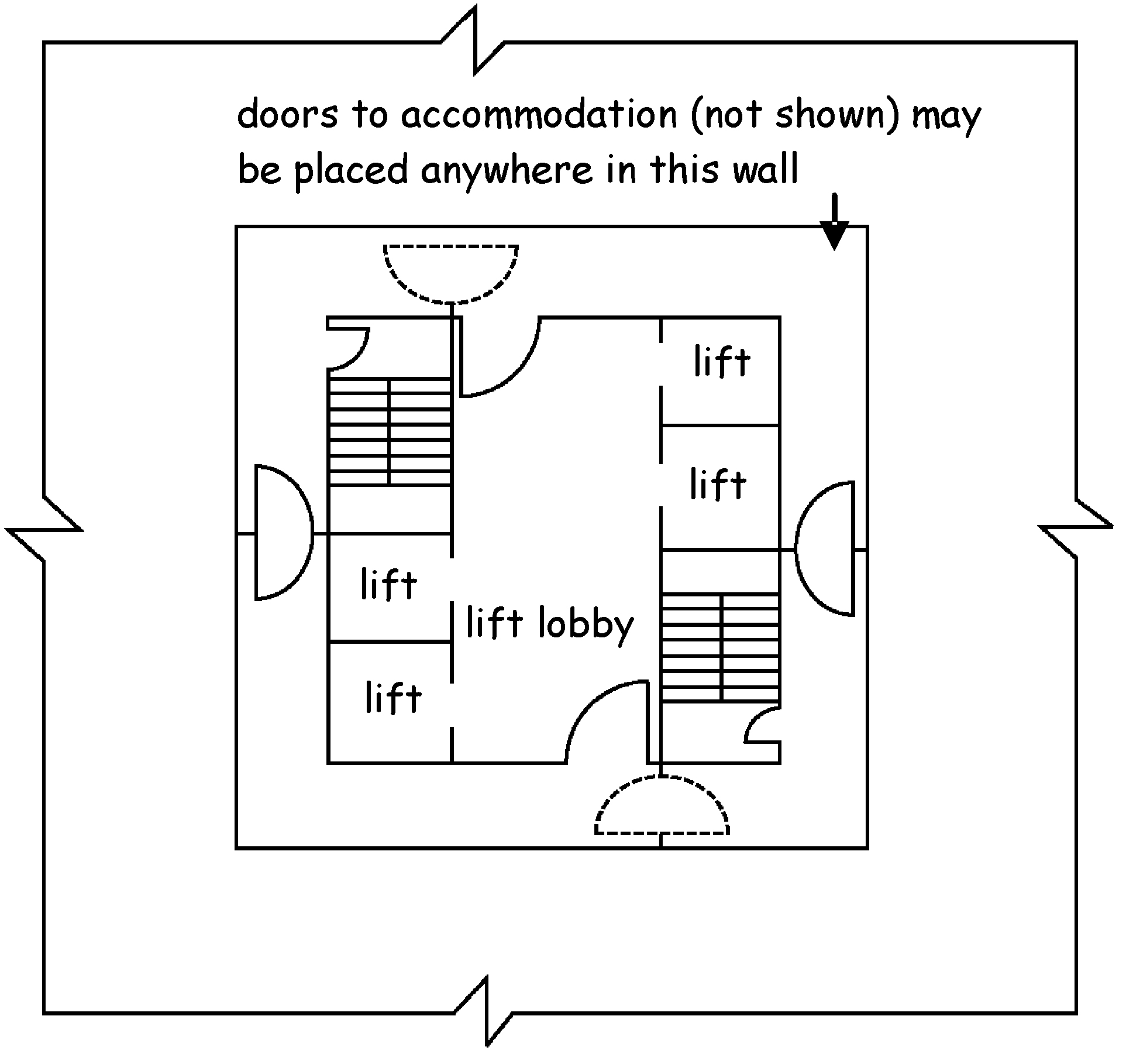
2.9.33 Escape routes in a central core
To reduce risk of smoke spread to more than 1 escape stair, corridor or lobby, a building with more than 1 escape route contained in a central core, should be planned so that the exits from the storey are remote from one another, and so that no 2 exits are approached from the same lift hall, common lobby or undivided corridor or linked by any of these other than through self-closing fire doors.
2.9.34 Escape stairs in basements
The limited natural ventilation available in a basement can lead to rapid heat and smoke build up. The heat and smoke generated can be forced up through any opening such as a door into a stairway. This means that fire-fighting in under-ventilated compartments must be approached with caution before opening the door to the basement storey.
There is also a risk that disoriented occupants could continue their escape to the basement storey instead of escaping through the ground storey.
In order to minimise these risks, a wall or screen (including a self-closing fire door) with a medium fire resistance duration should be provided between the ground storey of the protected zone and the basement storey.
2.9.35 Construction of escape stairs
In buildings of more than 1 storey where the means of escape is via an escape stair, this will also be the route from which the fire and rescue services will fight the fire and effect rescue. The possibility that the escape stair may be affected by fire breaking out or being deliberately set in the stairway has to be considered. Consequently the escape stair should be provided with additional protection.
Therefore, every part of an escape stair (including landings) and the floor of a protected zone or protected lobby, should be constructed of non-combustible material. However this does not apply to:
-
any handrail, balustrade or protective barrier on an escape stair
-
an escape stair which connects 2 or more levels within a single-storey where the difference in height between the highest and lowest level is not more than 1.8m
-
an escape stair from a gallery, catwalk or openwork floor constructed in accordance with the guidance in clause 2.9.25
-
a floor finish (e.g. laminate flooring) applied to the escape stair (including landings) or to the floor of a protected zone or protected lobby.
If a protected zone has an external wall that projects beyond the face of a building or is set back in a recess, the protected zone may be vulnerable to fire following the break out of fire through an adjacent window, door or other opening. Radiated heat or flames from the fire may impede occupants using the protected zone to escape.
Therefore where any part of a protected zone is not more than 2m from, and makes an angle of not more than 135° with any part of an external wall of another part of the building, the escape stair should be protected against fire for a distance of 2m, by construction with a:
The designer can choose which wall should be fire resisting and may include fire resisting facades or other fixed glazing, or any other opening protected against fire. However it is not sufficient to use the final exit door as a barrier between the occupants escaping and the fire. In such cases the external wall adjoining the protected zone at the final exit should be protected against fire as described above.
Escape routes will normally lead to the final exit door of the building, which leads to a safe place in the outside air from which occupants can freely disperse. An exit can also lead to an external escape stair, a flat roof or access deck giving access to a place of safety.
Protection of external route of escape - in some cases it may not be possible to freely disperse away from the building (e.g. where the final exit door discharges to an enclosed outdoor space). In such cases, where there is only 1 route of escape, the external wall of the building within 2m of the route of escape should have a short fire resistance duration for integrity up to 1.1m above the adjoining ground. This does not apply to sub-floor vents.
An external escape stair is an unenclosed escape stair, which is open to the external air and provides occupants with an escape route, which leads to a place of safety. They present additional hazards to occupants evacuating a building in the event of fire. This is because the escape stair will be exposed to the possible effects of inclement weather and occupants who are unfamiliar with the escape routes can feel less confident using an unenclosed stair high above the ground.
Therefore, an external escape stair should only serve a building where:
-
the top most storey height is not more than 7.5m, and
-
the building or part of the building is not accessible to the general public, and
-
in the case of a residential care building or a hospital, the stair is intended to be used by staff only.
In order to protect the occupants from fire and smoke during evacuation, the external escape stair should be protected against the outbreak of fire from within the building. Where the escape stair which has a total rise of more than 1.6m, every part of the external wall including fixed windows or glazing, self-closing fire doors (other than a door opening from the top storey) or any other opening not more than 2m from the escape stair, should have a short fire resistance duration. Fire protection below an escape stair should be extended to the lowest ground level.
An external escape stair with a total rise of not more than 1.6m from which occupants can freely disperse, is considered to be low enough above the ground to present minimal risk to occupants leaving the building and as a result, fire protection need not be provided.
Due to the likely smoke dissipation to atmosphere; service openings including ventilation ducts not more than 2m from the escape stair may be protected by heat activated sealing devices or systems.
Escape across flat roofs and access decks can be hazardous because the surface can be exposed to adverse weather conditions and in the case of flat roofs, may also have obstructions or no edge protection. Therefore, escape routes over flat roofs should only be used where the building or part of the building is inaccessible to the general public and there is more than 1 escape route from the room or storey leading to the flat roof.
In order to protect occupants from fire, a flat roof or an access deck forming part of an escape route should have medium fire resistance duration for the width of the escape route and for a further 3m on either side of the escape route. Every wall not more than 2m from either side of the escape route, should have a short fire resistance duration up to a height of at least 1.1m measured from the level of the escape route.
In addition, there should be no exhausts of any kind less than 2m from the escape route unless protected by heat activated sealing devices or systems (see clause 2.1.14). A wall or protective barrier at least 1.1m high may be necessary on each side of the escape route or along the edge of the access deck when the escape route is across a flat roof or access deck (see Section 4 Safety).
The final exit to a place of safety at ground level, should present as little restriction as possible to occupants using wheelchairs or having other disabilities. Final exits should therefore be provided with:
-
a level platt except for any nominal slope for drainage having an area of at least 1.2m x 1.2m, and
-
a threshold that does not form a trip hazard and will permit unassisted egress to occupants in a wheelchair (see Section 4 Safety).
When altering existing buildings, it may not always be reasonably practicable to achieve the above recommendations.